Introduction, Cornet connectors, 1 cornet connectors – ElmoMC AC Input Digital Servo Drives-Cornet Cable Kit User Manual
Page 4
1. Introduction
This document provides the wiring details for the cables used to connect Cornet digital
servo drives with the end-user application. The servo drive-side pinouts are provided in
Chapter 3 of the drive’s installation guide.
The cables come in two lengths: 2 meters (6 ½ feet) and 5 meters (16 ½ feet). The cable
length is indicated in the cable part number by use of an extended suffix to indicate 5
meter length. For example, cable CBL-DAUX is a 2 meter cable while
CBL-DAUX-5 is a 5 meter cable.
CBL-RJ45CAN2, is an exception, it is only 20 cm long.
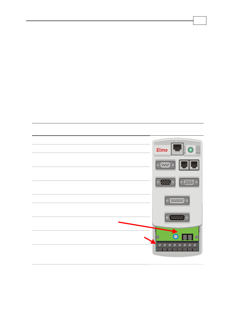
1.1 Cornet Connectors
The Cornet has the following connectors:
Type
Function
Port on Cornet
Connector Location
8-pin RJ-45
RS-232
COMM. 1
9 pin D-sub socket
Analog Input
ANALOG INPUTS
8-pin RJ-45, RJ-45
CAN … CAN
(CANopen)
COMM. 2
15-pin high-density
D-sub plug
Digital Inputs
COMMITTED I/O
15-pin high-density
D-sub socket
Digital Outputs
GENERAL I/O
15-pin D-sub socket
Main feedback
FEEDBACK A
15-pin D-sub plug
Auxiliary
Feedback
FEEDBACK B
2-pin terminal strip
Molex
Auxiliary power
supply
+,
−
8-pin terminal block
Molex
Mains and motor
power
M1, M2, M3, PE,
PE, AC1, AC2, AC3
AC3
AC2
AC1
PE
M3
M2
M1
FEEDBACK B
FEEDBACK A
ANALOG INPUTS
COMMITTED I/O
COMM.2
GENERAL I/O
COMM.1
COR0018A
PE
Table
1-1: Connectors on the Cornet
Cornet Cable Kits
MAN-CBLKIT-COR (Ver. 1.0)
1