I/o cables, Analog inputs (cbl-a001-5), Analog – ElmoMC AC Input Digital Servo Drives-Cornet Cable Kit User Manual
Page 10
4. I/O Cables
•
Analog Inputs
•
Digital Inputs ("COMMITTED I/O")
•
Digital Outputs ("GENERAL I/O")
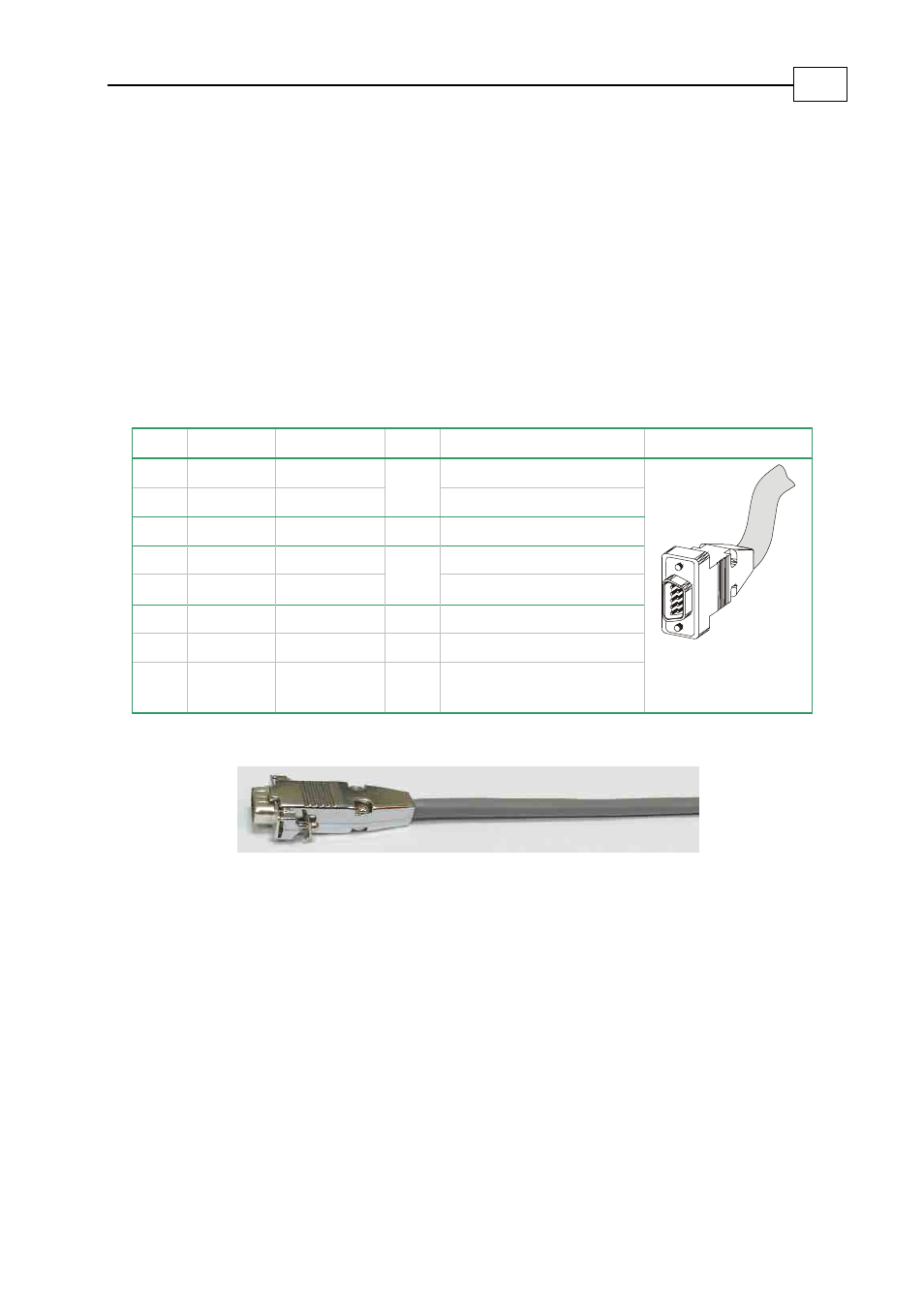
4.1 Analog Inputs (CBL-A001
-5
)
The digital input cable is a 24-AWG shielded cable. It is connected using an 9-pin D-sub
plug.
Pin Color
Signal
Pair Function
Pin Position
1
Brown
ANLIN1+
Analog Input 1
2
White
ANLIN1-
Pair
Analog Input 1
3
Yellow
ANLRET Analog
Ground
4
Red
ANLIN2+
Analog Input 2
5
Blue
ANLIN2-
Pair
Analog Input 2
6 Pink
GND
Common
Return
9 Green
GND
Common
Return
-
Drain Wire soldered to
connector body
CEL0040A-DWG
COR016A
Figure 4: Analog Input Cable (Part No. CBL-A001
-5
)
9 Pin
D-sub
Plug
Cornet Cable Kits
MAN-CBLKIT-COR (Ver. 1.0)
7
See also other documents in the category ElmoMC Hardware:
- Gold Line Digital Servo Drives-Gold Bell (84 pages)
- Gold Line Digital Servo Drives-Gold DC Bell (61 pages)
- Gold Line Digital Servo Drives-Gold Whistle (85 pages)
- Gold Line Digital Servo Drives-Gold Solo Whistle (61 pages)
- Gold Line Digital Servo Drives-Gold Drum Ver 1_400 D-Sub connectors (67 pages)
- Gold Line Digital Servo Drives-Gold Drum Ver 1_400 RJ-45 connectors (67 pages)
- Gold Line Digital Servo Drives-Gold DC Whistle (61 pages)
- Gold Line Digital Servo Drives-Gold Drum HV (102 pages)
- Gold Line Digital Servo Drives-Gold Duo (59 pages)
- Gold Line Digital Servo Drives-Gold Solo Whistle Cable Kit (16 pages)
- Gold Line Digital Servo Drives-Gold Drum Cable Kit RJ-45 connectors (17 pages)
- Gold Line Digital Servo Drives-Gold DC Whistle Cable Kit (13 pages)
- Gold Line Digital Servo Drives-Gold Drum HV Cable Kit (18 pages)
- Gold Line Digital Servo Drives-Gold Duo Cable Kit (12 pages)
- Gold Line Digital Servo Drives-Gold Guitar (84 pages)
- Gold Line Digital Servo Drives-Gold Solo Guitar (65 pages)
- Gold Line Digital Servo Drives-Gold Cello (59 pages)
- Gold Line Digital Servo Drives-Gold Trombone (92 pages)
- Gold Line Digital Servo Drives-Gold Solo Trombone (110 pages)
- Gold Line Digital Servo Drives-Gold DC Trombone (69 pages)
- Gold Line Digital Servo Drives-Gold Tuba (81 pages)
- Gold Line Digital Servo Drives-Gold Bassoon (66 pages)
- Gold Line Digital Servo Drives-Gold Solo Guitar Cable Kit (12 pages)
- Gold Line Digital Servo Drives-Gold Cello Cable Kit (15 pages)
- Gold Line Digital Servo Drives-Gold Solo Trombone Cable Kit (16 pages)
- Gold Line Digital Servo Drives-Gold DC Trombone Cable Kit (15 pages)
- Gold Line Digital Servo Drives-Gold Tuba Cable Kit (20 pages)
- Gold Line Digital Servo Drives-Gold Bassoon Cable Kit (16 pages)
- ExtrIQ Gold Line Servo Drives-Gold Hornet (88 pages)
- ExtrIQ Gold Line Servo Drives-Gold Solo Hornet (90 pages)
- ExtrIQ Gold Line Servo Drives-Gold Eagle (68 pages)
- ExtrIQ Gold Line Servo Drives-Gold Hawk (90 pages)
- ExtrIQ Gold Line Servo Drives-Gold Panther (64 pages)
- ExtrIQ Gold Line Servo Drives-Gold Tiger (64 pages)
- Multi-Axis Motion Controller-Gold Maestro (32 pages)
- SimplIQ Digital Servo Drives-Bell Installation Guide (57 pages)
- SimplIQ Digital Servo Drives-Bell Getting Started (94 pages)
- SimplIQ Digital Servo Drives-Bell Command Reference (315 pages)
- SimplIQ Digital Servo Drives-Bell Evaluation Board User Guide (93 pages)
- SimplIQ Digital Servo Drives-Tweeter Installation Guide (71 pages)
- SimplIQ Digital Servo Drives-Whistle DC Installation Guide (75 pages)
- SimplIQ Digital Servo Drives-Whi-Solo Installation Guide (69 pages)
- SimplIQ Digital Servo Drives-Whi-Solo Cable Kit (10 pages)
- SimplIQ Digital Servo Drives-Whi-Duo Installation Guide (69 pages)
- SimplIQ Digital Servo Drives-Whi-Trio Installation Guide (62 pages)