Digital inputs and outputs – ElmoMC Gold Line Digital Servo Drives-Gold Drum Ver 1_400 RJ-45 connectors User Manual
Page 47
Gold Drum (RJ-45 Connectors) Installation Guide
MAN-G-DRUM(RJ45)IG-EC (Ver. 1.400)
||Digital Inputs and Outputs
47
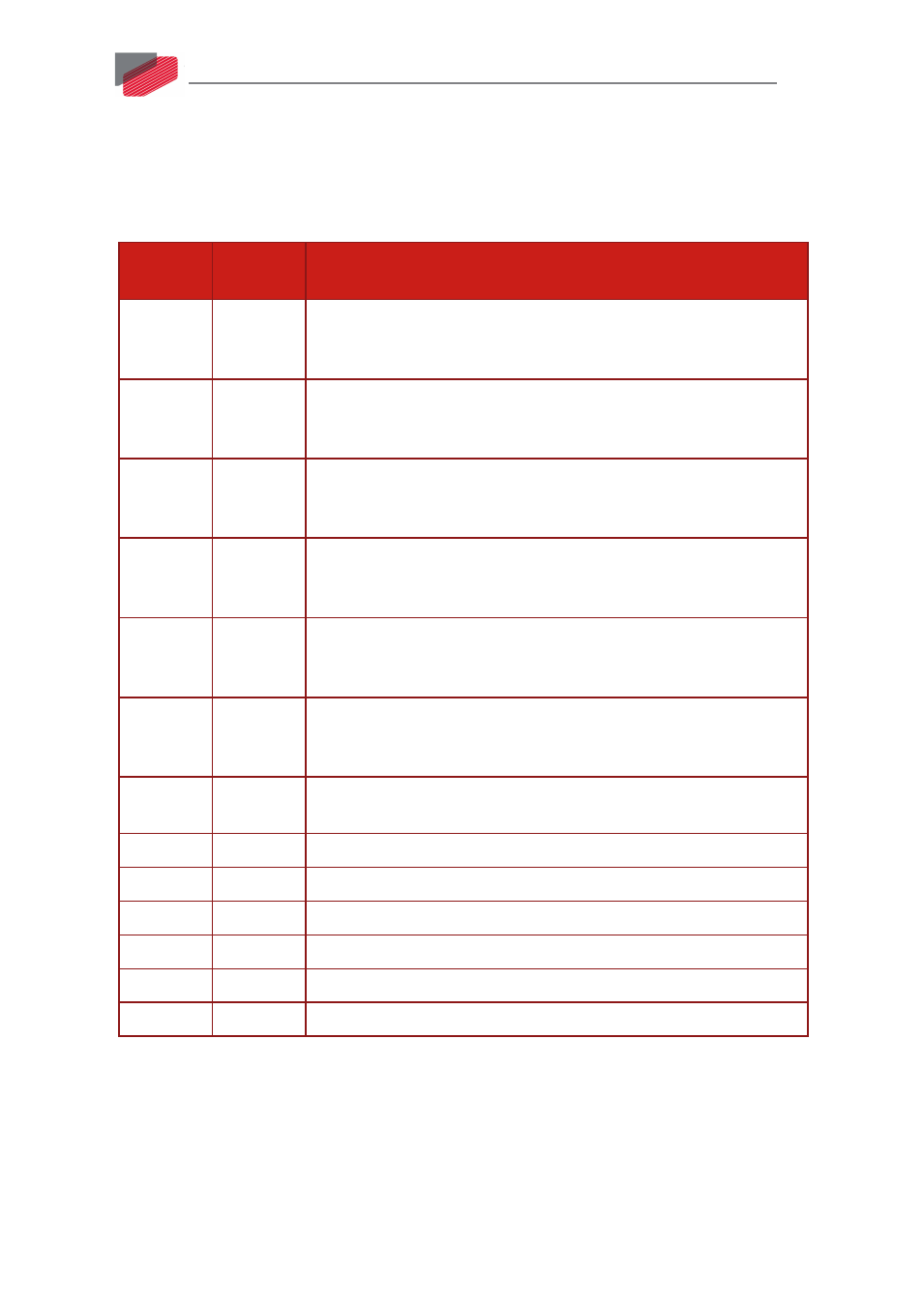
9.11. Digital Inputs and Outputs
The Gold Drum Port C connector is a D-Type connector with 15 high density male pins. Refer to
Chapter 11 in the in the MAN-G-Panel Mounted Drives Hardware manual for full details.
The following table lists the digital input pin assignments.
I/O Pins
(P4)
Signal
Function
1
IN1
High Speed, programmable input 1 (event capture, home, general
purpose, RLS, FLS, INH, PWM & direction input, pulse & direction
input)
2
IN2
High Speed, programmable input 2 (event capture, home, general
purpose, RLS, FLS, INH, PWM & direction input, pulse & direction
input)
7
IN3
High Speed, programmable input 3 (event capture, home, general
purpose, RLS, FLS, INH, PWM & direction input, pulse & direction
input)
8
IN4
High Speed, programmable input 4 (event capture, home, general
purpose, RLS, FLS, INH, PWM & direction input, pulse & direction
input)
11
IN5
High Speed, programmable input 5 (event capture, home, general
purpose, RLS, FLS, INH, PWM & direction input, pulse & direction
input)
12
IN6
High Speed, programmable input 6 (event capture, home, general
purpose, RLS, FLS, INH, PWM & direction input, pulse & direction
input)
6
INRET1-6
Programmable inputs 1 to 6 return for the standard version
Programmable positive input 1 to 6 for the Sink version
3
OUT1
Programmable output 1
4
OUT2
Programmable output 2
5
OUT3
Programmable output 3
13
OUT4
Programmable output 4 or STO Output
10, 15
VDD
Supply for out 1-4
9, 14
VDDRET
Supply return for out 1-4