Det-Tronics EA2100CG Eagle 2000 Communication Gateway User Manual
Page 35
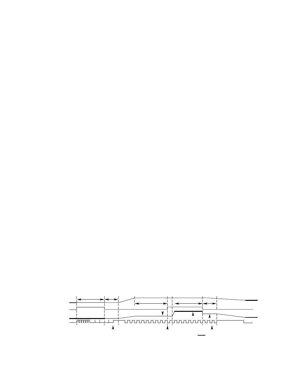
CALIBRATION ALGORITHM B (Type Codes 5, 6)
Normal Calibration
1.
Hold the mode select button on the side of the
transmitter enclosure for about 10 seconds. (See
Figure 30.) The transmitter cycles through the set-
points and the display starts to blink. Release the
mode select button. Input 1 on the communication
module goes active. The red LED on the communi-
cation module blinks at a 2 Hz rate for 3 seconds
while input 1 is active.
2.
The communication module calibrate LED flashes at
a 1 Hz rate to indicate that it is ready for the zero
input. The calibrate bit in the status word is set.
3.
The transmitter calibrates the sensor zero value for
the 4 ma output.
4.
The transmitter display is on steady and input 1
goes inactive.
5.
The communication module records the uncalibrat-
ed value in the calibration log and calibrates the
zero value. The calibrate LED goes on steady.
6.
Apply the calibration gas to the sensor.
7.
The transmitter display flashes. The communication
module calibrate LED blinks at a 1 Hz rate when the
input increases.
8.
Input 1 goes active when the transmitter input is
stable.
9.
The communication module records the uncalibrat-
ed value in the calibration log.
10. The transmitter completes its calibration. Input 1
goes inactive when the transmitter display is steady.
The communication module calibrates the span
value and the calibrate LED goes on steady.
11. Remove the calibration gas.
12. The communication module waits until the analog
value drops below 4% full scale.
13. The calibration is complete. The calibrate LED
goes off and the calibrate bit in the status word is
reset.
If the calibration is not completed within 10 minutes, the
previous calibration values are restored and the calibra-
tion is logged as aborted. The calibrate LED blinks at a
4 Hz rate, the calibrate bit in the status word is reset,
and the calibration fault bit in the status word is set.
If the sensor input drops to zero, a fault is signaled and
the calibration is aborted. The red communication mod-
ule LED blinks at a 4 Hz rate, the calibration fault bit is
set, and the calibrate bit is reset.
CAUTION
If the sensor current should drop to zero during
calibration, synchronization between the communi-
cation module and the transmitter may be lost,
depending on the calibration timing. Resetting the
communication module and the transmitter is
required, followed by another calibration.
Calibration After Sensor Replacement
1.
Open the junction box cover and press the sensor
replacement switch. Close the cover.
2.
The calibrate bit in the status word is set.
3.
Replace the sensor and perform a normal calibra-
tion.
The communication module will not signal a fault when
the input drops to zero due to removal of the sensor.
The calibration will not be aborted after 10 minutes.
Calibration values will be stored in the first register.
31
95-8424
3 SEC
3 SEC
3 SEC
3 SEC
3 SEC
3 SEC
3 SEC
3 SEC
3 SEC
ACCEPT ZERO
ACCEPT SPAN
ACCEPT ZERO
ACCEPT ZERO
ACCEPT SPAN
FRESH AIR
REMOVE GAS
SPAN GAS
ZERO GAS
3O SEC MIN
3O SEC MIN
3O SEC MIN
RECORD SPAN
TRENDING SPAN
REED SWITCH
ANALOG IN
LED
REED SWITCH
ANALOG IN
LED
REED SWITCH
ANALOG IN
LED
U8800 INPUT
ANALOG IN
LED
IN ONE
A1555
ACCEPT ZERO
ACCEPT SPAN
3 SEC
3 SEC
OLD SPAN
CALIBRATED SPAN
1
SEC
UNCONTROLLED ANALOG SIGNAL
UNCONTROLLED ANALOG SIGNAL
UNCONTROLLED ANALOG SIGNAL
UNCONTROLLED ANALOG SIGNAL
A1555
A1555
A1555
3O SEC MIN
3 SEC
3 SEC
3 SEC
ACCEPT ZERO
ZERO
IN ONE
ANALOG IN
LED
A1555
UNCONTROLLED ANALOG SIGNAL
Figure 30—Calibration Algorithm "B"