Det-Tronics EA2100CG Eagle 2000 Communication Gateway User Manual
Page 25
S5 – Hardware Serial Port Configuration
1 and 2
Channel 0 not used. Leave switches open.
3
Close if RS-232 is used.
4
Close if RS-422 is used. (Macintosh uses
RS-422.)
5 and 6
Channel 0 not used. Leave switches open.
7 and 8
Close switches.
S6 – Software Serial Port Configuration
1, 2, and 3 Determine the desired baud rate, then refer
to Table 6 for the proper switch settings.
(19,200 is recommended.)
4
Leave switch open (no parity).
5
Leave switch open (odd parity).
6
Leave switch open (1 stop bit).
7
Close switch (8 data bits).
8
Leave switch open.
S7 – Modbus Address
Set switches to match Modbus slave address. Setting
must be different for each gateway, unless redundant
gateways are used. (Backup gateway must have same
address as main gateway.) “0” is not a valid address.
S8 – Network Configuration
1 and 2
Set gateway address switches according to
Table 7.
3 to 5
Not used. Leave open.
6
Close for non-latching gateway relays.
7
Close switch if gateway is to function as a
backup gateway. Switch must be open for
main or auxiliary gateway.
8
Close for main gateway, open for all other
gateways.
21
95-8424
1
2
3
4
5
6
7
8
9
1
2
3
4
5
6
7
8
9
COMMUNICATION MODULE/DCU
18
17
16
15
14
13
12
11
10
RED
BLACK
GREEN
SENSOR
1
2
3
4
5
6
7
8
9
10
11
12
13
14
15
16
17
18
19
20
21
22
23
24
25
26
27
28
29
30
31
32
422 TXD
+
422 TXD
–
CHASSIS GND
+
–
422 RXD
+
422 RXD
–
EXT RESET
COM
232 TXD
232 RXD
COM
A
B
A
B
C
NO
NC
C
NO
NC
C
NO
NC
C
NO
NC
C
NO
NC
CHASSIS GND
GATEWAY
K1
K2
K3
K4
FAULT
+
–
24 VDC POWER INPUT
NETWORK IN
NETWORK OUT
A
B
A
B
+
+
–
–
RELAY COMMON
+
–
4 TO 20 MA IN
IN 2
COM
IN 1
COM
NC
NO
DIGITAL INPUT 2
DIGITAL INPUT 1
RELAY
DETECTOR POWER
(24 VDC)
COMMUNICATION MODULE/DCU
18
17
16
15
14
13
12
11
10
24 VDC POWER INPUT
NETWORK IN
NETWORK OUT
+
–
4 TO 20 MA IN
IN 2
COM
IN 1
COM
NC
NO
DIGITAL INPUT 2
DIGITAL INPUT 1
RELAY
24 VDC
NET 0
NET 1
24 VDC
A1588
22 AWG SHIELDED TWISTED PAIR
WIRING TYPE
RED
BLACK
GREEN
SENSOR
DETECTOR POWER
(24 VDC)
CHASSIS
CHASSIS
A
B
A
B
+
+
–
–
RELAY COMMON
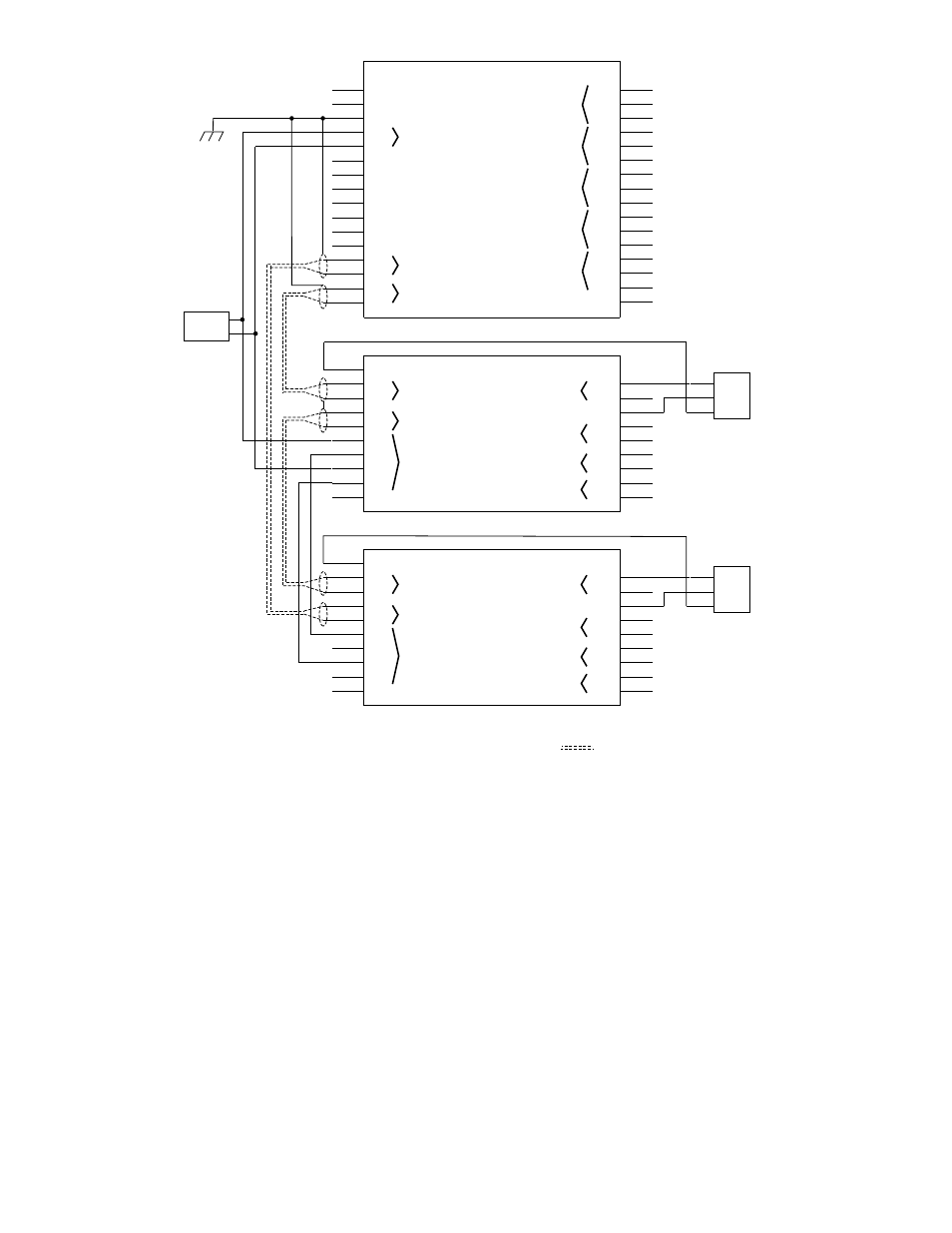
Figure 19—A Typical Application – Communication Modules or DCUs with Toxic Gas Sensors