Communication module and dcu wiring, Typical applications – Det-Tronics EA2100CG Eagle 2000 Communication Gateway User Manual
Page 23
COMMUNICATION MODULE
AND DCU WIRING
1.
Determine the best mounting locations for the
detectors. Whenever practical, detectors should be
placed where they are easily accessible for
calibration. Gas sensors should be pointing down to
minimize the accumulation of contaminants on the
filter and to ensure proper operation. Junction boxes
should be electrically connected to earth ground.
2.
Install the detectors as directed in the detector
instruction manual.
3.
Remove the cover from the junction box.
NOTE
Do not apply power to the system with the junction
box cover removed unless the area has been de-
classified.
4.
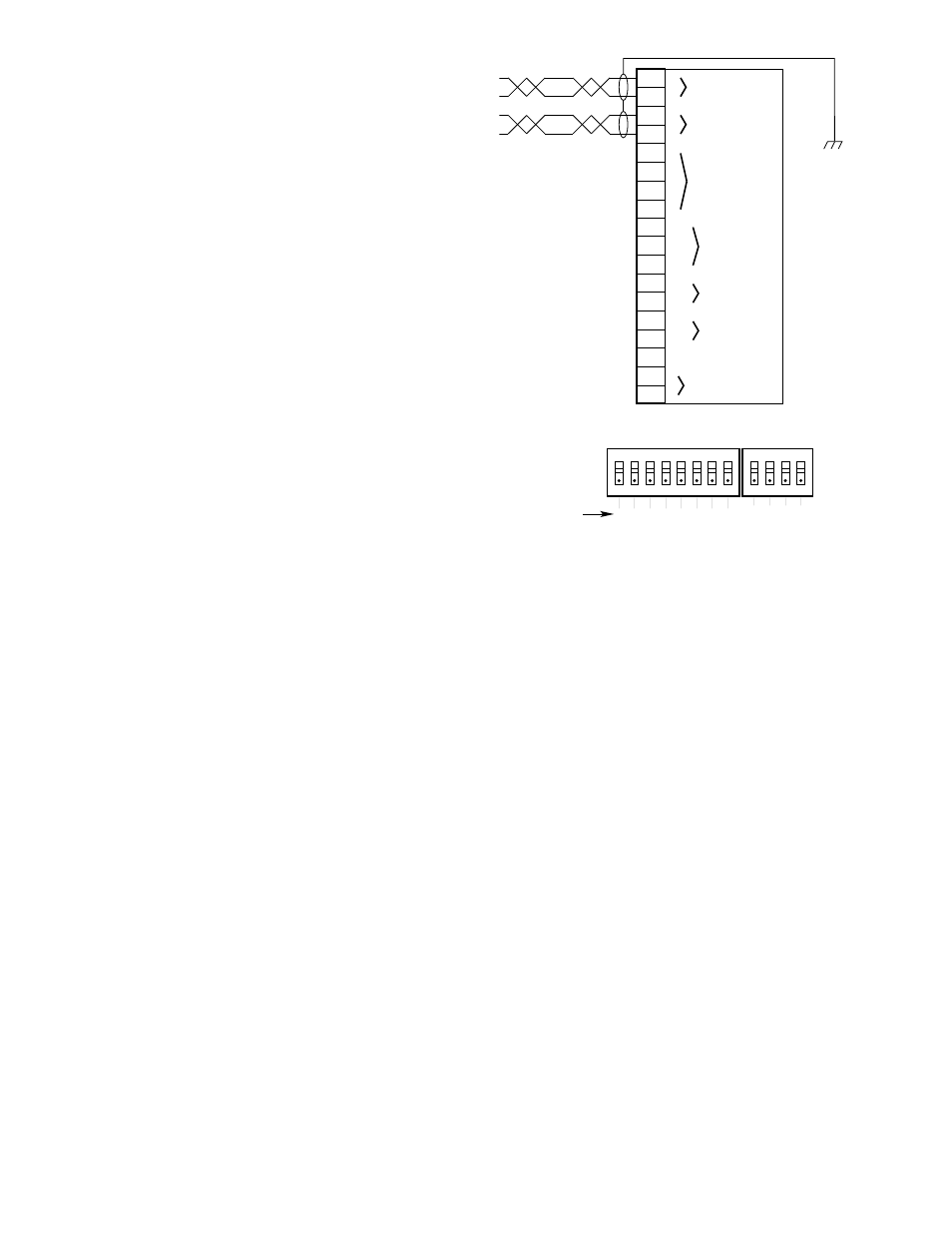
Connect external system wiring to the appropriate
terminals on the terminal block inside the junction
box. See Figure 16.
CAUTION
The gateway and communication modules will be
damaged if power is inadvertently applied to the
communication lines. The communication module
is protected against damage caused by switching
polarity of the power lines.
5.
Check the wiring to ensure proper connections,
then pour the conduit seals and allow them to dry (if
conduit is being used).
6.
Set the node address for the communication mod-
ule. Valid addresses are from 1 to 250. If the
address is set to zero or an address above 250, the
communication module will ignore the switch set-
ting. Duplicated addresses are not automatically
detected. All modules with the same address will
report on that address. The status word will show
the latest update, which could be from any of the
reporting modules at that address.
Address selection is accomplished by setting rocker
switches on the DIP switch assembly on the commu-
nication module circuit board. Each rocker switch
has a specific binary value (Figure 17). The node
address is equal to the added value of all closed
rocker switches. All open switches are ignored. For
example: for node No. 5, close rocker switches 1
and 3 (binary values 1 + 4); for node 25, close rock-
er switches 1, 4 and 5 (binary values 1 + 8 + 16).
7.
Install the electronic module inside the junction box.
Refer to Figure 7. Be sure that the ribbon cable is
properly connected.
8.
Inspect the junction box O-ring to be sure that it is in
good condition and properly installed. Lubricate the
O-ring and the threads of the junction box cover with
a thin coat of an appropriate grease to ease installa-
tion and ensure a water-tight enclosure. The recom-
mended lubricant is a silicone free polyalphaolefin
grease, available from Det-Tronics. If the installation
uses catalytic type combustible gas sensors, it is
imperative that lubricants containing silicone not be
used, since they will cause irreversible damage to
the sensor. Place the cover on the junction box.
Tighten only until snug. Do not over tighten.
TYPICAL APPLICATIONS
Figure 18 illustrates a typical system consisting of com-
munication modules used with a U8700 or U8800
Transmitter.
Figure 19 illustrates communication modules or DCUs
with toxic gas sensors.
Figure 20 shows communication modules or DCUs with
combustible gas sensors and transmitters. (A DCU has
the combustible gas transmitter mounted inside the
DCU enclosure.)
Figure 21 illustrates a typical system consisting of com-
munication modules with various flame detection devices.
19
95-8424
–
GROUND SHIELD
AT ONE END ONLY
A1599
1
2
3
4
5
6
7
8
9
10
11
12
13
14
15
16
17
18
A
A
B
B
22 AWG LEVEL 4
SHIELDED TWISTED PAIR
24 VDC POWER INPUT
NETWORK IN
NETWORK OUT
+
+
–
C
NO
NC
COM
IN 1
COM
IN 2
4 TO 20 MA
–
+
DIGITAL INPUT 1
DIGITAL INPUT 2
RELAY
DETECTOR POWER
(24 VDC)
1
2
3
4
5
6
7
8
1
2
3
4
1
2
4
8
16 32 64 128
OPEN
OPEN
}
LEAVE IN
OPEN POSITION
NODE ADDRESS EQUALS THE ADDED VALUE
OF ALL CLOSED ROCKER SWITCHES
A1557
BINARY VALUE
Figure 17—Communication Module Address Switches
Figure16—Wiring Configuration for Communication Module and DCU