Gateway wiring – Det-Tronics EA2100CG Eagle 2000 Communication Gateway User Manual
Page 24
GATEWAY WIRING
Field Wiring Connector
The gateway is furnished with a field wiring connector
backplate that incorporates pressure type screw termi-
nals for connecting the external wiring and a circuit
board edge connector for attaching to the gateway.
The use of a mounting rack is required for mounting the
gateway. The backplate is attached to the back of the
rack to allow easy removal of the gateway without dis-
turbing the wiring. See Figures 22 and 23.
The gateway is designed for installation in a non-haz-
ardous area.
Figure 24 shows the terminal configuration.
Typical Application
Figure 25 illustrates a typical system consisting of a
gateway, communication modules and an OIS. One
communication module is shown with a U8700/U8800
Transmitter.
Figure 26 shows the communication loop and power
wiring for a typical system consisting of a gateway, com-
munication module, network extender and relay module.
CAUTION
The gateway will be damaged if power is inadver-
tently applied to the communication lines. The
gateway is protected against damage caused by
switching polarity of the power lines.
GATEWAY SWITCH SETTINGS
The gateway contains four 8-position DIP switch assem-
blies that are used for:
– Selecting the serial port hardware and software
parameters
– Setting the gateway Modbus address
– Selecting the main gateway
– Setting the gateway address.
Refer to Figure 27 to identify the function of the DIP
switches. Refer to Figure 28 to locate the DIP switch
assemblies on the side of the gateway.
NOTE
Close switch to enable function.
20
1
2
3
4
5
6
7
8
9
18
17
16
15
14
13
12
11
10
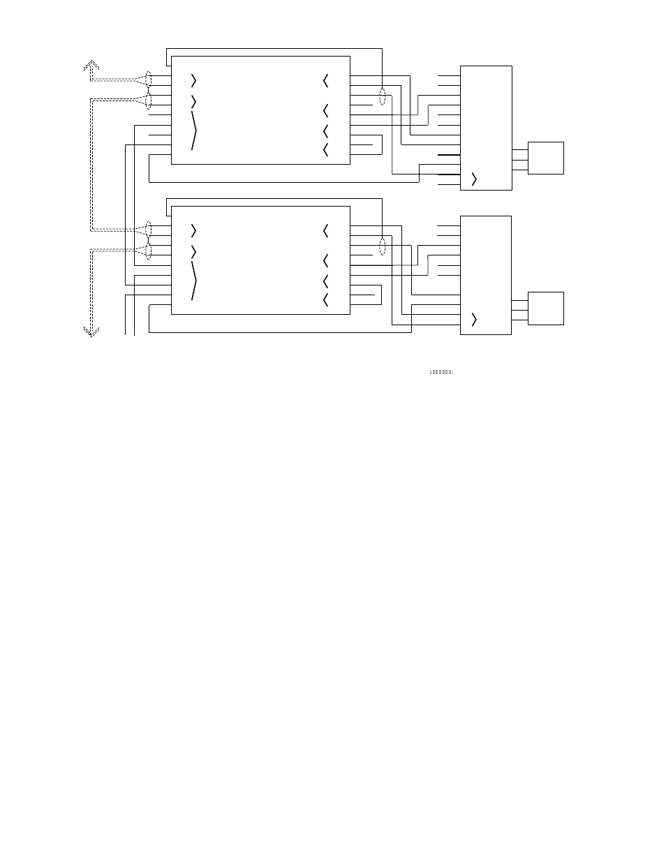
CHASSIS GROUND
ALARM
ALARM
CALIBRATE
CALIBRATE
FAULT
FAULT
4 TO 20 MA
RESET
+
–
EAGLE U8800
SENSOR
A1650
1
2
3
4
5
6
7
8
9
18
17
16
15
14
13
12
11
10
CHASSIS GROUND
COMMUNICATION MODULE
22 AWG SHIELDED TWISTED PAIR
NOTES
1. WIRING TYPE
2.SHIELD CONNECTED AT ONE END ONLY.
GATEWAY/
COM MOD
– +
POWER
SUPPLY
GATEWAY/
COM MOD
ALARM
ALARM
CALIBRATE
CALIBRATE
FAULT
FAULT
+
–
RESET
–
+
EAGLE U8700
(JUMPERED FOR NON-ISOLATED CURRENT OUTPUT)
SENSOR
POWER
24 VDC POWER INPUT
NETWORK IN
NETWORK OUT
A
B
A
B
+
+
–
–
RELAY COMMON
+
–
4 TO 20 MA IN
IN 2
COM
IN 1
COM
NC
NO
DIGITAL INPUT 2
DIGITAL INPUT 1
RELAY
DETECTOR POWER
(24 VDC)
24 VDC POWER INPUT
NETWORK IN
NETWORK OUT
A
B
A
B
+
+
–
–
RELAY COMMON
+
–
4 TO 20 MA IN
IN 2
COM
IN 1
COM
NC
NO
DIGITAL INPUT 2
DIGITAL INPUT 1
RELAY
DETECTOR POWER
(24 VDC)
COMMUNICATION MODULE
4 TO 20 MA
POWER
Figure 18—A Typical Application – Communication Module with an Eagle U8700 or U8800 Detector