Det-Tronics EA2100CG Eagle 2000 Communication Gateway User Manual
Page 33
29
95-8424
CALIBRATION ALGORITHM A
(Type Codes 1, 2, 3, 4) for Gas Detectors
Normal Calibration
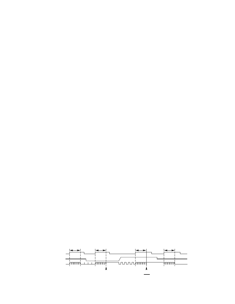
1.
Activate the reed switch or input 1 on the communi-
cation module (See Figure 29). The red LED blinks
at a 2 Hz rate while the reed switch or input 1 is
closed.
2.
After the reed switch has been closed for 3 sec-
onds, the calibrate LED on the communication mod-
ule flashes at a 1 Hz rate, indicating that it is ready
for the zero input. The calibrate bit in the communi-
cation module status word is set.
3.
Apply the zero input (4 ma).
4.
Activate the reed switch or input 1 on the communi-
cation module. The red LED will blink at a 2 Hz rate
for 3 seconds while the reed switch or input 1 is
closed.
5.
After the reed switch or input 1 has been closed for
3 seconds, the communication module records the
uncalibrated value in the calibration log and cali-
brates the zero value. The calibrate LED goes on
steady.
6.
Apply the calibration gas.
7.
The calibrate LED blinks at a 1 Hz rate when the
input increases.
8.
Activate the reed switch or input 1 on the communi-
cation module. The red LED blinks at a 2 Hz rate
while the reed switch or input 1 is closed.
9.
The communication module records the uncalibrat-
ed value in the calibration log and calibrates the
span value after the reed switch or input 1 is on for
3 seconds.
10. The calibrate LED goes on steady.
11. Remove the span gas and return the analog input to
normal.
12. Activate the reed switch or input 1 on the communi-
cation module. The red LED blinks at a 2 Hz rate for
3 seconds while the reed switch or input 1 is closed.
13. The calibration is complete. The calibrate LED turns
off and the calibrate bit in the status word is reset.
If the calibration is not completed within 12 minutes, the
previous calibration values are restored and the calibra-
tion is logged as aborted. The calibrate LED flashes at
a 4 Hz rate, the calibrate bit in the status word is reset
and the calibration fault bit is set.
Calibration After Sensor Replacement
1.
Open the junction box cover and press the sensor
replacement switch.
2.
The calibrate LED on the communication module
flashes at a 1 Hz rate, indicating it is ready for the
zero input. The calibrate bit in the status word is
set.
3.
Replace the sensor and apply the zero input (4 ma).
4.
Activate the reed switch or input 1 on the communi-
cation module. The red LED blinks at a 2 Hz rate for
3 seconds while the reed switch or input 1 is closed.
5.
The communication module records the uncalibrat-
ed value in position one of the calibration log and
calibrates the zero value. The calibrate LED goes
on steady.
6.
Apply the calibration gas.
7.
The calibrate LED blinks at a 1 Hz rate when the
input increases.
8.
Activate the reed switch or input 1 on the communi-
cation module. The red LED blinks at a 2 Hz rate for
3 seconds while the reed switch or input 1 is closed.
9.
The communication module records the uncalibrat-
ed value in the first register of the calibration log
and calibrates the span value.
10. The calibrate LED goes on steady.
11. Remove the span gas and return the analog input to
normal.
12. Activate the reed switch or input 1 on the communi-
cation module. The red LED blinks at a 2 Hz rate for
3 seconds while the reed switch or input 1 is closed.
13. The calibration is complete. The calibrate LED
turns off and the calibrate bit in the status word is
reset.
Pressing the sensor replacement switch aborts the cali-
bration and starts over. Resetting the communication
module will abort sensor replacement.
3 SEC
3 SEC
3 SEC
3 SEC
3 SEC
3 SEC
3 SEC
3 SEC
3 SEC
ACCEPT ZERO
ACCEPT SPAN
ACCEPT ZERO
ACCEPT ZERO
ACCEPT SPAN
FRESH AIR
REMOVE GAS
SPAN GAS
ZERO GAS
3O SEC MIN
3O SEC MIN
3O SEC MIN
RECORD SPAN
TRENDING SPAN
REED SWITCH
ANALOG IN
LED
REED SWITCH
ANALOG IN
LED
REED SWITCH
ANALOG IN
LED
U8800 INPUT
ANALOG IN
LED
IN ONE
A1555
ACCEPT ZERO
ACCEPT SPAN
3 SEC
3 SEC
OLD SPAN
CALIBRATED SPAN
1
SEC
UNCONTROLLED ANALOG SIGNAL
UNCONTROLLED ANALOG SIGNAL
UNCONTROLLED ANALOG SIGNAL
UNCONTROLLED ANALOG SIGNAL
A1555
A1555
A1555
3O SEC MIN
3 SEC
3 SEC
3 SEC
ACCEPT ZERO
ZERO
IN ONE
ANALOG IN
LED
A1555
UNCONTROLLED ANALOG SIGNAL
Figure 29—Calibration Algorithms "A" and "F"