Installation checklist – Det-Tronics EA2100CG Eagle 2000 Communication Gateway User Manual
Page 31
INSTALLATION CHECKLIST
The following checklist is provided as a means of dou-
ble checking the system to be sure that all phases of
system installation are complete and have been per-
formed correctly.
1.
Junction boxes are mounted securely and detectors
are pointing in the proper direction.
2.
All cable shields are properly grounded.
3.
All junction box covers are tightly installed.
4.
Explosion-proof conduit seals or watertight glands
have been installed at all junction box entries.
5.
Sensor and communication network wiring is correct.
6.
Power wiring is installed and power source is opera-
tional.
7.
External loads are properly connected.
8.
DIP switches on the communication modules are set
correctly. Record this information for future reference.
9.
Gateway switches are set as desired. Record this
information for future reference.
10. Gateway is properly installed in the mounting rack.
11. Proper ventilation is provided (if needed) to prevent
equipment over-heating.
Proceed to System Startup.
27
95-8424
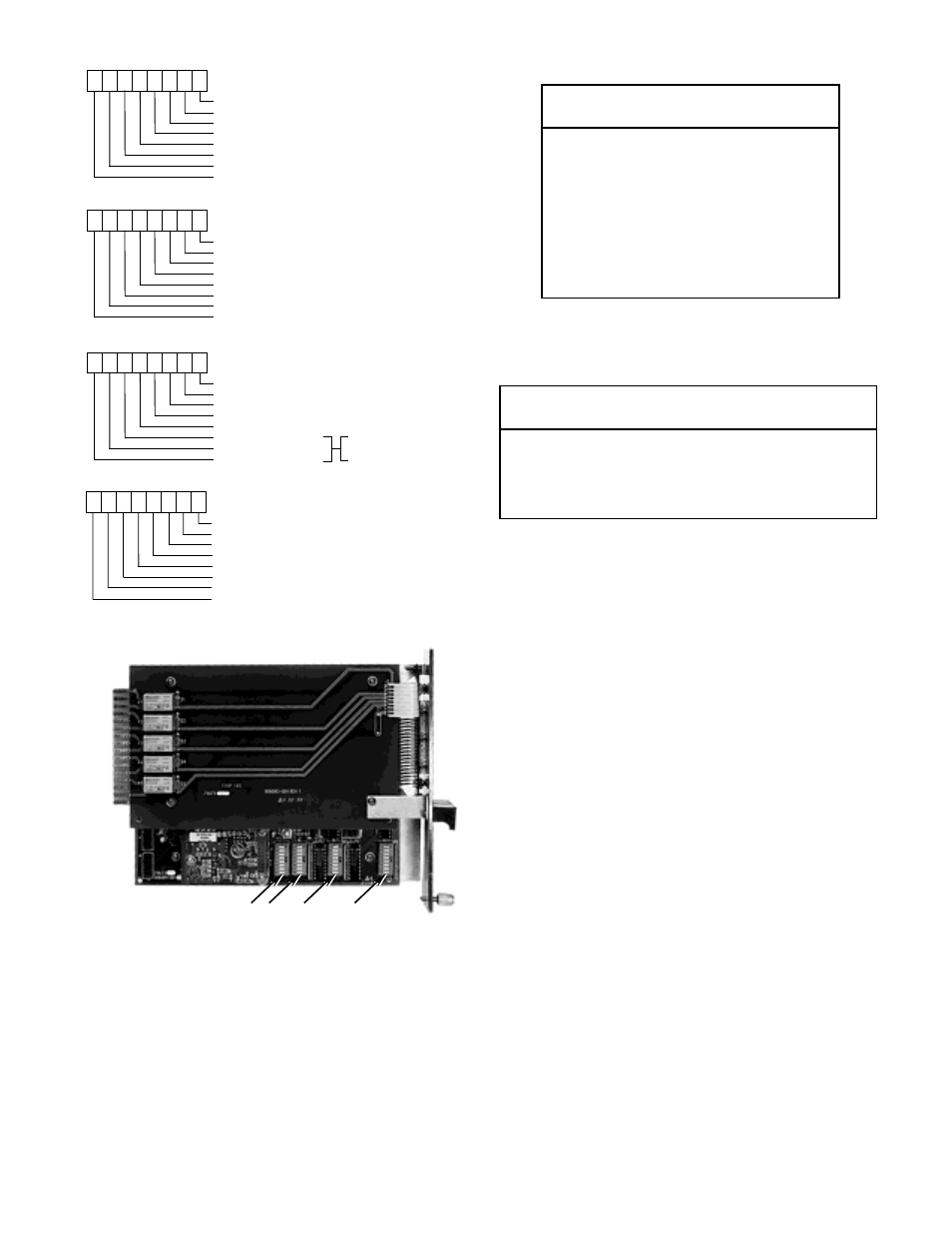
PARITY ENABLE (OFF = NO PARITY, ON = PARITY ENABLED)
BAUD RATE BIT 2 (MSB)
BAUD RATE BIT 1
BAUD RATE BIT 0 (LSB)
PARITY TYPE (OFF = ODD, ON = EVEN)
NUMBER OF STOP BITS (OFF = 1, ON = 2)
RS-422/RS-485 (OFF = RS-422, ON = RS-485)
NUMBER OF DATA BITS (OFF = 7, ON = 8)
1
2
3
4
5
6
7
8
S6 SOFTWARE SERIAL PORT CONFIGURATIONS (CHANNEL 1 ONLY)
0 = 1200
1 = 2400
2 = 9600
3 = 19200
4 = 57600
5 = 38400
6 = 300
7 = 4800
A1554
CHANNEL 1 RS-422 RECEIVER ENABLE
CHANNEL 1 RS-232 RECEIVER ENABLE
CHANNEL 0 RS-422 RECEIVER ENABLE
CHANNEL 0 RS-232 RECEIVER ENABLE
CHANNEL 0 RS-422 TRANSMITTER TERMINATION
CHANNEL 0 RS-422 RECEIVER TERMINATION
CHANNEL 1 RS-422 RECEIVER TERMINATION
CHANNEL 1 RS-422 TRANSMITTER TERMINATION
1
2
3
4
5
6
7
8
S5 HARDWARE SERIAL PORT CONFIGURATIONS
MODBUS ADDRESS BIT 3
MODBUS ADDRESS BIT 2
MODBUS ADDRESS BIT 1
MODBUS ADDRESS BIT 0 (LSB)
MODBUS ADDRESS BIT 4
MODBUS ADDRESS BIT 5
MODBUS ADDRESS BIT 7 (MSB)
MODBUS ADDRESS BIT 6
1
2
3
4
5
6
7
8
S7 MODBUS ADDRESS
UNDEFINED
UNDEFINED
GATEWAY ADDRESS BIT 1 (MSB)
GATEWAY ADDRESS BIT 0 (LSB)
UNDEFINED
NON-LATCHING GATEWAY RELAYS
MAIN/AUXILIARY GATEWAY (OFF = AUX, ON = MAIN)
BACKUP GATEWAY
1
2
3
4
5
6
7
8
S8 LON CONFIGURATION
S8
S7
S6
S5
A1546
BAUD RATE
SWITCH POSITIONS
1
2
3
1200
Op
Op
Op
2400
Cl
Op
Op
9600
Op
Cl
Op
19,200
Cl
Cl
Op
57,600
Op
Op
Cl
38,400
Cl
Op
Cl
300
Op
Cl
Cl
4800
Cl
Cl
Cl
GATEWAY FUNCTION
SWITCH POSITIONS
1
2
Main Gateway
Op
Op
1st Aux. Gateway
Cl
Op
2nd Aux. Gateway
Op
Cl
3rd Aux. Gateway
Cl
Cl
Figure 27—Gateway DIP Switch Assignments
Figure 28—Gateway DIP Switch Location
Op = Open
Cl = Closed
Table 6—Baud Rate Selection – Switches S6-1, S6-2, S6-3
Table 7—Gateway Address – Switches S8-1, S8-2
Op = Open
Cl = Closed