Det-Tronics MOS H2S Gas Sensor User Manual
Page 11
95-8532
1.4
9
DISPLAy AND CONTROLS, OPTIONS,
DEFAULTS
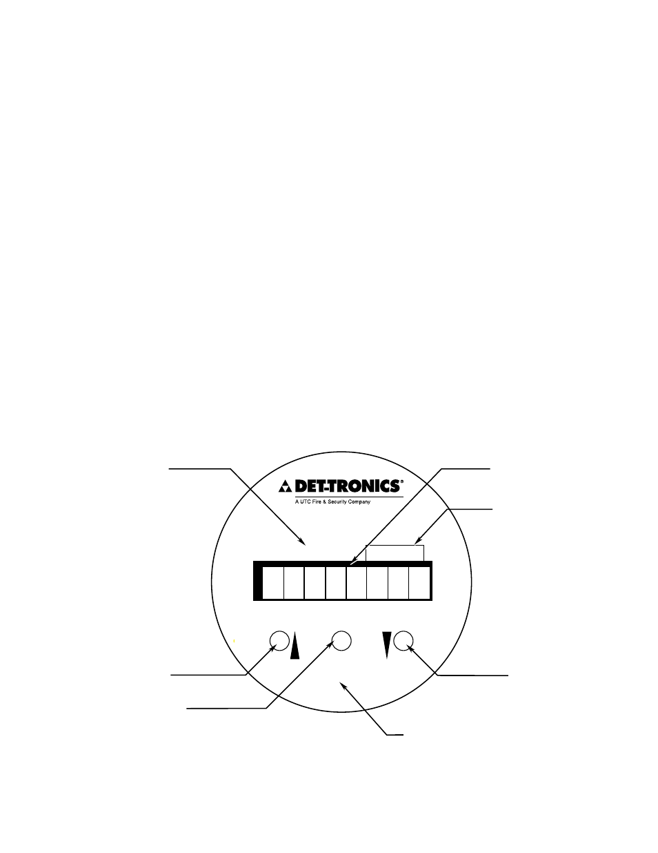
DISpLaY aND CONTROLS
The Infiniti uses an eight character display for identifying
system status conditions and sensor input, a magnetic
reed switch for resetting the unit and entering different
operating modes, and pushbuttons for programming and
calibrating the system. See Figure 11 for the location
of indicators and pushbuttons and Tables 1 and 2 for
descriptions.
External Reset
The default reset input terminal, when grounded
momentarily, initiates a reset only. However, if the “EXT”
“CAL” option is programmed “YES” during the Infiniti
setup procedure, the external reset duplicates the
magnetic reed switch (Cal Magnet) and can be used to
perform calibration.
pROGRaMMING OpTIONS
Operating Range
The operating range limits and the corresponding default
setpoints and calibration gases are as follows:
Measurement Range:
0 to 100
High Alarm
10 to 90
Default = 20
Low Alarm
5 to 50
Default = 10
Auxiliary Alarm
5 to 90
Default = 20
Calibration Gas
40
Default = 40*
*Calibration gas is not selectable.
The default setting for relay operation is normally de-
energized with non-latching contacts (except fault,
which is normally energized with no faults, and high
alarm, which is always latching). The default setting for
the optional External Reset Pushbutton is “No External
Cal” enabled. The default setting for calibration mode
(automatic or manual) is automatic mode.
IMPORTANT
The range setting of the transmitter must match
the output range of the sensor being used or the
system will fail to operate correctly. For a MOS
H
2
S sensor, the range setting for the transmitter
must be 0 to 100 ppm.
SENSOR INPUT READING
A1659
}
INCREASE PUSHBUTTON
SETUP/ACCEPT PUSHBUTTON
CAL/RESET MAGNETIC REED SWITCH
(ACTIVATED BY HOLDING CAL MAGNET TO THIS SIDE OF TRANSMITTER
APPROXIMATELY TWO INCHES DOWN FROM THE WINDOW)
DECREASE PUSHBUTTON
ALARM STATUS INDICATORS
ALARM HISTORY INDICATOR
LO
DECREASE
INCREASE
ACCEPT
CAL/RESET
SETUP
AUX
ALARM
HI
Figure 11—Infiniti Transmitter Controls and Indicators