Det-Tronics X3302 Multispectrum IR Flame Detector User Manual
Page 9
7
95-8576
9.2
Relay and 0-20 mA Output Models
Follow the instructions below to install the X3302.
1. Make field connections following local ordinances
and guidelines in this manual.
– Figure 4 shows the wiring terminal strip located
inside the detector’s integral junction box.
– Figure 5 shows the wiring terminal identification for
the X3302 Flame Detector.
– Figure 6 shows an EOL resistor installed within the
integral wiring compartment of the detector (refer to
“EOL Resistors” for details).
– Figures 7 and 8 provide examples of typical
installations with a X3302 wired to a fire alarm
panel.
– If the detector is equipped with a 0 to 20 mA output,
refer to Figures 9 through 12.
2. Check all field wiring to be sure that the proper
connections have been made.
IMPORTANT
Do not test any wiring connected to the detector
with a meg-ohmmeter. Disconnect wiring at
the detector before checking system wiring for
continuity.
3. Make the final sighting adjustments and use a 14 mm
hex wrench to ensure that the mounting arm assembly
is tight.
EOL Resistors (Not Used with EQp Model)
To ensure that the insulating material of the wiring
terminal block will not be affected by the heat generated
by EOL resistors, observe the following guidelines when
installing the resistors.
1. Required EOL resistor power rating must be 5
watts minimum.
NOTE
EOL resistors must be ceramic, wirewound
type, rated 5 watts minimum, with actual power
dissipation not to exceed 2.5 watts.
This applies
to ATEX/IEC installations only.
2. Resistor leads should be cut to a length of
approximately 1 1/2 inches (40 mm).
3. Bend the leads and install the EOL resistor as
shown in Figure 6.
4. Maintain a 3/8 inch (10 mm) minimum gap between
the resistor body and the terminal block or any
other neighboring parts.
NOTE
The EOL resistor can only be used within the
flameproof terminal compartment. Unused conduit
entries shall be closed with suitable blanking
elements.
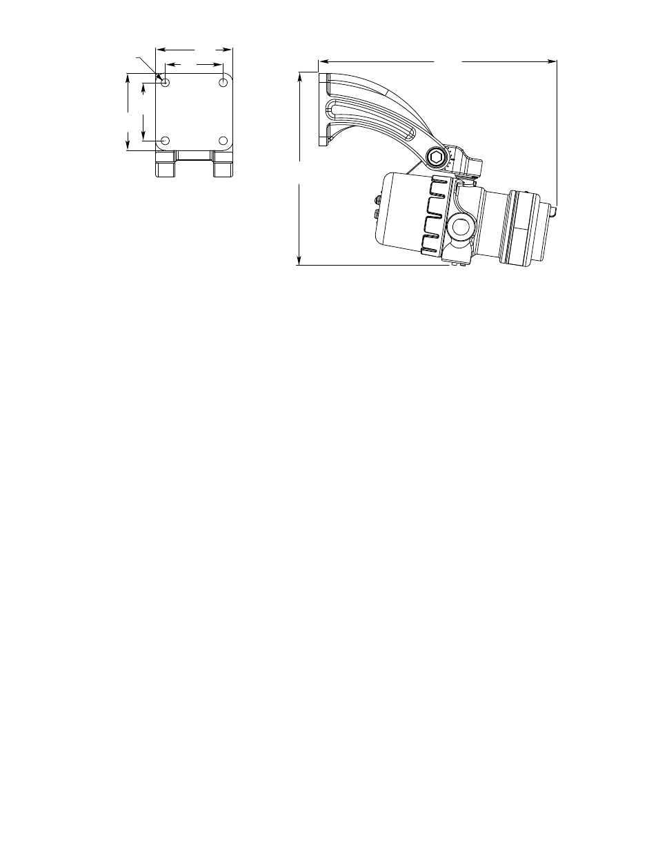
13.1
(33.3)
10.6
(27.0)
4.0
(10.2)
4.0
(10.2)
3.0
(7.6)
3.0
(7.6)
4X ø0.42
(1.1)
F2069
NOTE: THIS ILLUSTRATION SHOWS THE
DETECTOR MOUNTED AT THE 10° MINIMUM.
THESE DIMENSIONS WILL CHANGE BASED
ON THE DETECTOR’S MOUNTING ANGLE.
Figure 3—Q9033 Mounting Arm without Collar Attachment Dimensions in Inches (cm)
(See Figure 1 for Correct Detector Orientation.)