Startup procedure, Connect the cable leadwires from the flexvu ud, Infiniti u – Det-Tronics PIR9400 PointWatch Infrared Hydrocarbon Gas Detector User Manual
Page 16: Transmitter, mount and wire the infiniti u, Transmitter as shown in figure, And as described in the infiniti u, Instruction manual
14
95-8440
9.3
Mounting and Connecting Procedure
for Detector Separation
The PIRTB can be mounted to a wall or post, or it can
be suspended by the conduit if this does not result in
excessive vibration. A
3/8
inch spacer may be needed
between the termination box and the mounting surface
to allow adequate room for the sensor and calibration
accessory. The termination box should be electrically
connected to earth ground.
1. Lubricate the sensor threads with low vapor pressure
silicone grease, then install the sensor in the conduit
entry of the termination box. It should be tight to
ensure an explosion-proof installation, however, do
not
overtighten.
2. Connect the detector wires to the terminal strip in the
termination box as shown in Figures
22
and
23
.
3. Connect the cable leadwires from the FlexVu
UD
10
, Infiniti U
9500
or termination box to the same
terminals inside the separated termination box. Do
not
ground the shield at the termination box. Ground
the sensor wire shield at the transmitter end only.
4. Check the connections inside the termination box
and place the cover on the termination box.
5. If used with the Infiniti U
9500
Transmitter, mount and
wire the Infiniti U
9500
Transmitter as shown in Figure
22
and as described in the Infiniti U
9500
Instruction
Manual.
STARTUP PROCEDURE
1. Inhibit the output loads that are actuated by the
system to prevent activation of these devices.
2. Check that the detector has been wired properly.
3. Apply power to the system and allow the detector to
operate for a minimum of
2
hours, then check zero
and verify gas response. Perform a zero and span
calibration, if necessary.
NOTE
If the device is being used with a gas other than
methane, it must be calibrated with
50%
LFL of the
gas selected with the gas selection switch.
4. Place the system in normal operation by reactivating
the output loads.
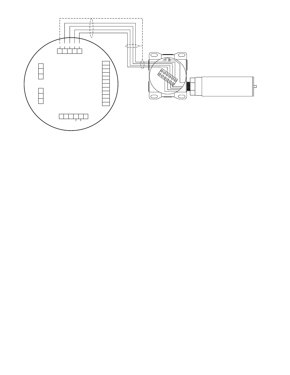
NOTE 1
CONNECT THE GREEN SENSOR LEAD TO THE CHASSIS GROUND LUG
ON THE INSIDE BOTTOM OF THE STB ENCLOSURE.
NOTE 2
GROUND THE SHIELD AT THE DISPLAY UNIT END ONLY.
NOTE 3
HOUSINGS MUST BE ELECTRICALLY CONNECTED TO EARTH GROUND.
UD10
DISPLAY UNIT
POINTWATCH
DETECTOR
SEE NOTE 2
E2403
Sensor Connector
Power Supply Connector
Output Loop
Connector
MODBUS
Connector
R
ela
y Connect
or
P1
J2
J3
J4
P2
4-20 mA +
4-20 mA –
SHIELD
COM
RS485 A
RS485 B
HIGH ALARM COM
HIGH ALARM NC
HIGH ALARM NO
AUX ALARM COM
AUX ALARM NC
AUX ALARM NO
LOW ALARM COM
LOW ALARM NC
LOW ALARM NO
FAULT COM
FAULT NC
FAULT NO
24 VDC
–
24 VDC
+
SHIELD
24 VDC
–
24 VDC
+
SHIELD
SHIELD
C
ALIBR
A
TE
24 VDC
–
4-20 mA
24 VDC
+
P1-3
P1-2
P1-1
J2-3
J2-2
J2-1
J4-1
J4-2
J4-3
J4-4
J4-5
J4-6
J4-7
J4-8
J4-9
J4-10
J4-11
J4-12
J3-1
J3-2
J3-3
J3-4
J3-5
P2-6
P2-5
P2-4
P2-3
P2-2
P2-1
RED
YELLOW
WHITE
GREEN
SEE NO
TE 1
STB TERMINATION BOX
BLACK
Figure 23—Sensor Separation with FlexVu UD10 and PIR9400