Appendix a, Model gp16xx gas panel configuration worksheet – Det-Tronics GP16XX Standard Gas Panel User Manual
Page 16
1.1
95-8671
14
DETECTOR ELECTRONICS CORPORATION
6901 West 110th Street
Minneapolis, MN 55438
A
v
e
R
1
1
/
8
0
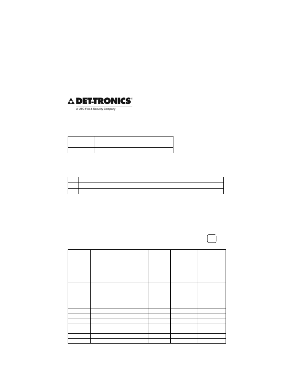
MODEL GP16XX GAS PANEL CONFIGURATION WORKSHEET
Date:
Customer:
PO#:
HARDWARE:
Maximum number of field devices is 16 (
i.e. the total of B & C cannot exceed 16)
A
Number of Analog Input Modules – AIM (Maximum of 2)
B
Number of 4-20 mA Field Devices (Maximum 8 per AIM)
C
Number of LON Field Devices
SOFTWARE:
Record detector model, gas range, low alarm, and high alarm set-points in the
table below.
FACTORY DEFAULT: Range = 0-100
Low Alarm = 20
High Alarm = 40
NOTE:
If factory defaults are acceptable rather than specified values check here
CHANNEL
DETECTOR
MODEL or PART #
RANGE
(0-xxxx)
LOW
ALARM
SET POINT
HIGH
ALARM
SET POINT
1
2
3
4
5
6
7
8
9
0
1
1
1
2
1
3
1
4
1
5
1
6
1
appenDiX a –
CONFIGURATION WORKSHEET
The purpose of the configuration worksheet is to establish user defined parameters prior to the shipment of the GP16XX
Gas Panel. Using the information collected from the worksheet, the packaged system solution will be shipped from the
factory pre-configured with all the options selected by the user. Field devices are ordered separately.
A PDF copy of the configuration worksheet can be found on our website.
NOTE
The worksheet must be completed during order placement.