Operation – Det-Tronics GP16XX Standard Gas Panel User Manual
Page 13
1.1
95-8671
11
operation
NOTE
After configuring a device, it is highly
recommended that calibration be performed
before operation.
CAlIBRATION
ImpoRtANt
The Calibration Active and Calibration Fault
indications are only available for LON devices, and
not for 4-20 mA devices. The following instructions
are specific to LON based devices.
In regards to monitoring calibration through the GP16XX,
the general calibration procedure is as follows:
1. Initiate calibration locally at the device.
2. Activate the Point Display within the Main screen
for the device in calibration. The "Calibration
Active" indicator becomes solid white when gas is
applied (Figure 11).
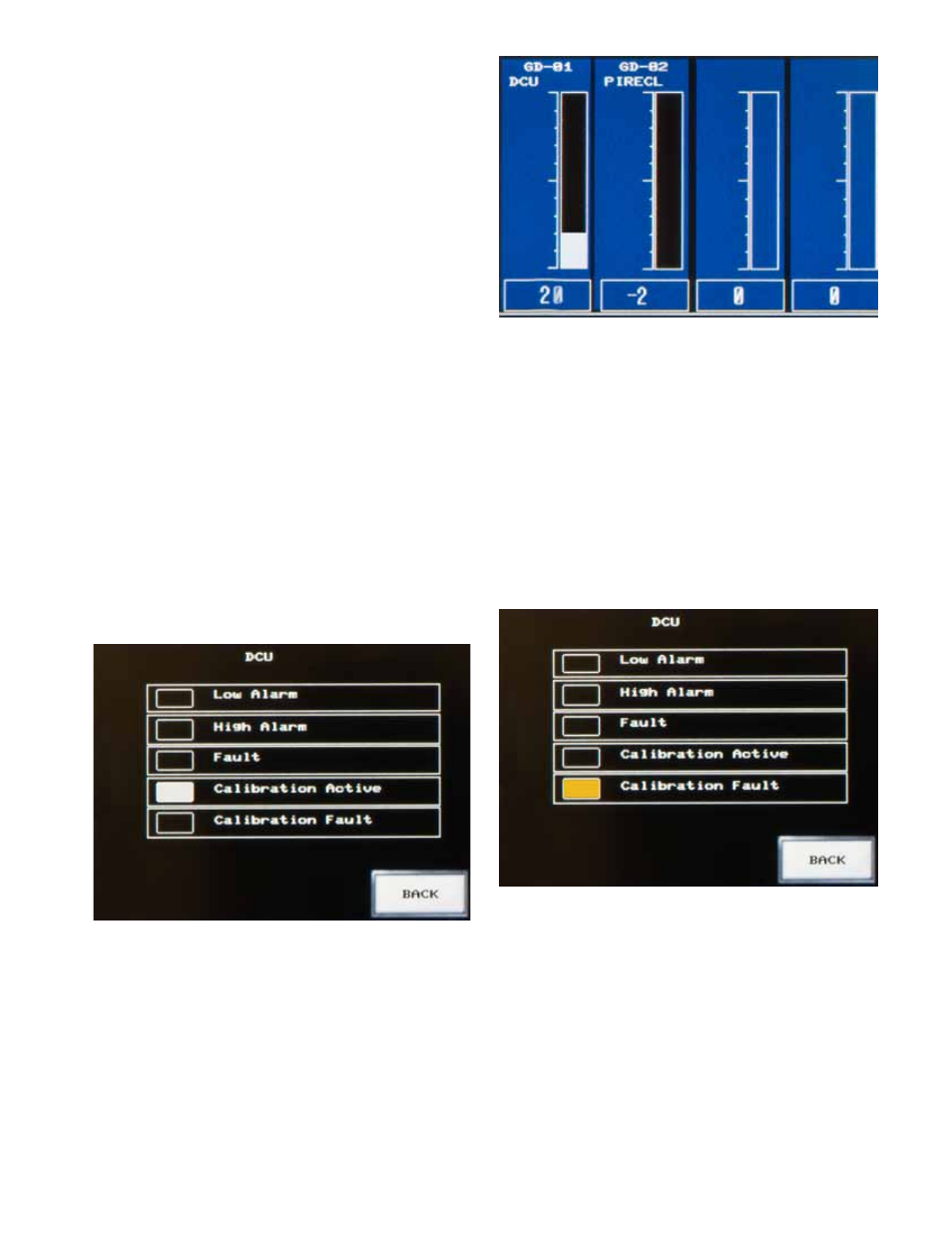
3. On the Main screen, the real time gas value will
rise above zero and the applied calibration gas is
indicated when the channel contains a solid white
bar (Figure 12).
4. When calibration is successful press the BACK
button to return to the Main screen.
Calibration Fault
Calibration faults are indicated on the Point Display
when the "Calibration Fault" indicator is solid yellow
(Figure 13). On the Main screen, the channel and the
FAULT button will flash yellow (Figure 14).
Consult the device specific instruction manual for
information on how to clear faults. The indication of the
fault will remain latched on the touch screen display until
it is corrected and the RESET button is pressed.
Figure 11—Calibration active Indication on Point Display
Figure 12—Real Time Gas Value and applied Gas on Main Screen
Figure 13—Calibration Fault Indication on Point Display