Det-Tronics GP16XX Standard Gas Panel User Manual
Page 15
1.1
95-8671
13
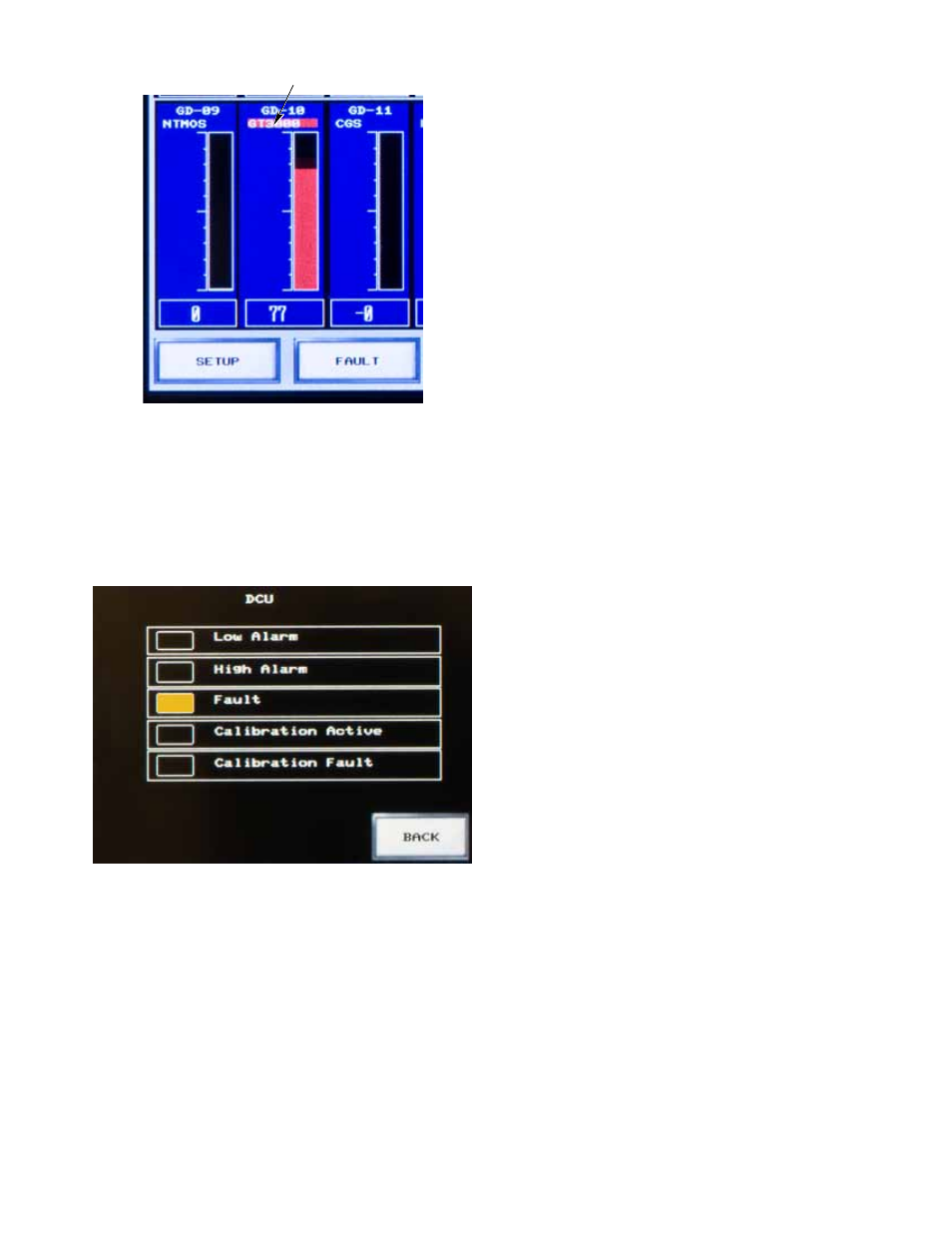
FAUlTS
Faults that are not associated with the calibration of a
device are indicated on the Point Display when the "Fault"
indicator is solid yellow (Figure 19).
trouBleshooting
For detailed troubleshooting information regarding the
GP16XX components and compatible devices, refer
to the EQP manual, 95-8533, or the device specific
instruction manual.
maintenance
Depending on the environment, the GP16XX does not
require specific maintenance, but the HMI touch screen
may become dirty and cause visibility problems. Avoid
using any solvent when cleaning a dirty panel. A damp
cloth is sufficient for wiping dirt from the HMI touch
screen.
replacement parts
The GP16XX devices are not designed to be repaired
in the field. If a problem should develop, first carefully
check for proper wiring, programming and calibration.
If it is determined that the problem is caused by an
electronic defect, please contact your local Det-Tronics
sales representative.
DeVice repair anD return
Prior to returning devices or components, contact
the nearest local Det-Tronics office so that a Return
Material Identification (RMI) number can be assigned.
A written statement describing the malfunction must
accompany the returned device or component to
expedite finding the cause of the failure
.
Pack the unit or component properly. Always use
sufficient packing material. Where applicable, use an
antistatic bag as protection from electrostatic discharge.
NOTE
Inadequate packaging that ultimately causes
damage to the returned device during shipment
will result in a service charge to repair the damage
incurred during shipment.
Return all equipment transportation prepaid to the factory
in Minneapolis.
orDering inFormation
When ordering a GP16XX, please complete the
configuration worksheet (Appendix A). The purpose of
the configuration worksheet is to establish user defined
parameters prior to the shipment of the GP16XX Gas
Panel. Using the information collected from the worksheet,
the packaged system solution will be shipped from the
factory pre-configured with all the options selected by
the user. Field devices are ordered separately.
A PDF copy of the configuration worksheet can be
found on our website.
Figure 19—Fault Indication on Point Display
Figure 18—Latched alarm Indication on Main Screen
LATCHED ALARM
INDICATION