Tally dascom 2610 – Dascom 2600 User Guide User Manual
Page 115
Tally Dascom 2610
102
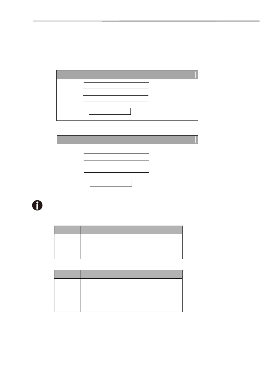
Interface cable (serial interface)
The cables used must be shielded. The cable shield must be connected to the connector
shield on both ends.
PC/AT(9 Pin) Printer(9 Pin)
RxD 2
3 TxD
TxD 3
2 RxD
CTS 8
4 DTR/RDY
SG 5
5 SG
DSR 6
DTR 4
PC/AT(25 Pin) Printer(9 Pin)
FG 1
FG
TxD 2
2 RxD
RxD 3
3 TxD
CTS 5
4 DTR/RDY
SG 7
5 SG
DSR 6
DTR 20
It depends on the menu setting whether DTR or RDY (Ready) is active at Pin 4.
◆ Input signals
Signal
Function
CTS
DSR
RxD
Clear to Send
Data Set Ready
Receive Data
◆ Output signals
Signal
Function
DTR
RTS
READY
TxD
Data Terminal Ready
Request to Send
Ready to receive data
Transmit Data
This manual is related to the following products:
See also other documents in the category Dascom Printers:
- DM-210 User Guide (53 pages)
- DT-210 User Guide (64 pages)
- 7106 User Guide (56 pages)
- 7106 Quick Start Guide (2 pages)
- 7106 Programmers Manual ZPL (76 pages)
- 7106 Programmers Manual DMX (156 pages)
- 7106 Peeler Installation and User Guide (14 pages)
- 7106 Ethernet Installation Guide (8 pages)
- 7106 Cutter Installation Guide (20 pages)
- 7106 PrintServer Manual (238 pages)
- 7106 WLAN Installation Guide (8 pages)
- 7106 Compact Ethernet Board (9 pages)
- 7010 Quick Start Guide (2 pages)
- 7010 Peeler Installation and User Guide (4 pages)
- 7010 Cutter Installation Guide (8 pages)
- MIP480 Flash Utility Operation Manual (4 pages)
- MIP480 User Guide (138 pages)
- MIP480 Quick Installation Guide (2 pages)
- 1325 User Guide (100 pages)
- 1430 User Guide (100 pages)
- 5130 Instructions on How to Flash Firmware (1 page)
- T5040 Programmers Application Manual (12 pages)
- T5040 User Guide (146 pages)
- T5040 Quick Start Guide (28 pages)
- T5040 Quick Start Guide (124 pages)
- T5040 Flash Utility Operation Manual (4 pages)
- LA800+ Quick Start Guide (176 pages)
- LA550N Quick Start Guide (156 pages)
- LA550N User Guide (146 pages)
- LA48N/LA48W Quick Start Guide (2 pages)
- LA48N/LA48W User Guide (206 pages)
- T2380 Installation Information Second Tractor (14 pages)
- T2380 User Guide IGP for Dot Matrix Printers (80 pages)
- T2380 Quick Installation Guide Cutting Device (134 pages)
- T2380 Web Panel Description - ETH-INT (25 pages)
- T2280+ Installation Sheet Face Down (54 pages)
- T2265+ Quick Start Guide (32 pages)
- T2265+ Quick Start Guide (144 pages)
- T2265+ Quick Start Guide (144 pages)
- T2265+ User Guide Automatic Sheet Feeder, Front (24 pages)
- T2250 RS232C/TTY Interface Module Operators Manual (44 pages)
- T2250 Installation Guide Automatic Sheet Feeder Rear (2 pages)
- T2250 Quick Reference Guide (2 pages)
- T2250 Quick Start Guide (134 pages)
- T2250 Quick Start Guide (30 pages)