Blower installation and placement, Figure 9, Figure 10 – Clarus Environmental Fusion Series Treatment Systems 2800/3200/3600/4000 User Manual
Page 8: Warning
8
© Copyright 2013. All rights reserved.
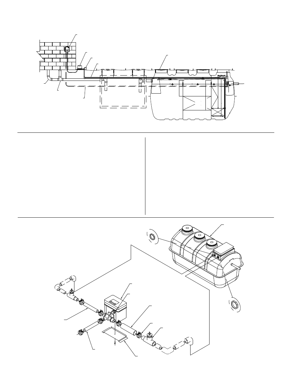
Figure 9
1. This product must be connected to a grounded, metallic,
permanent wiring system, or an equipment-grounding terminal
or lead on the product.
2. Place the blower where it is easily accessible for maintenance
and inspection.
3. Install the blower in an area where it will be protected from
damage and flooding. Also make certain the location has good
ventilation. DO NOT place the blower below water level as back-
siphoning can occur.
4. Install the blower on a foundation that is level and solid.
5. Excavate trench for air line from blower to the switching valve,
and trench for air lines from switching valve to Fusion
®
unit.
6. Install one 1" (25.4 mm) air line from the blower to the switching
valve. Piping should be less than 17' (5 m) from blower to
Fusion
®
unit. The recirculation line is ¾" (19 mm) and the
backwash line is 1" (25.4 mm).
7. The blower is provided with one discharge port. Install the
included air line PVC tees in the backwash and recirculation
lines.
8. Attach the small diameter black air tubing (included in the blower
box) to barbed fitting on PVC tee. Black air tubing and blower
cord should be routed to the control panel through conduit.
Attach the black air tubing line to the air pressure sensor barbed
fittings in the panel. (Figure 10) If air tubing is not connected to
backwash and recirculation lines, the panel will alarm.
9. Connect the remaining end of the PVC tee to the airline installed
in Step 6.
10. The switching valve is 100V and must be connected to the panel
through the use of the supplied transformer. See included
transformer installation instructions.
BLOWER INSTALLATION AND PLACEMENT
Figure 10
SK2930
SK2955
WARNING!
CLEANOUT
SEWER
ALARM FLOAT CONDUIT
INSTALLED BY CONTRACTOR
WHERE APPLICABLE
CLARUS FUSION
ALARM PANEL
BLOWER
SWITCH BOX
RISER AND LID
AIR LINES TO
TREATMENT UNIT
TO DISPERSAL
W.L
W.L
W.L
OPTIONAL SEPTIC TANK INSTALLATION
MAY BE REQUIRED BY
LOCAL OR STATE REGULATIONS
BACKWASH HOSE
SUPPLIED
(RED CONNECTION)
SWITCH BOX
AERATION HOSE
SUPPLIED
(BLUE CONNECTION)
MOUNTING BRACKET
CLAMP
BLOWER HOSE
SUPPLIED
ZFL TREATMENT UNIT
POWER CORD
AIR LINE SENSOR FITTING
RED CONNECTION
BACKWASH
BLUE CONNECTION
AERATION