Fusion, Operation and maintenance, continued, System diagram – Clarus Environmental Fusion Series Treatment Systems 2800/3200/3600/4000 User Manual
Page 14: Aeration chamber cleaning
14
1.
Aeration.
The aeration system must be flushed every maintenance
visit. There are two flushing methods; (A) Air flushing
and (B) Water flushing. Air flushing must be done every
maintenance visit. Water flushing must be done if there is
a sign of clogging in the Aeration Chamber (e.g. abnormal
increase in recirculation flow).
(A) Air flushing procedure:
• Close gray recirculation valve (2) all the way. (0%)
• Rotate blue aeration valve (1) back and forth from the
0% to the 100% position several times to flush.
• Set valves (1) and (2) back to the appropriate positions.
(See Recirculation Flow Adjustment, pg. 10)
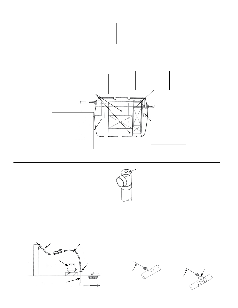
(B) Water flushing procedure: (See Fig. 20)
• Make sure that the blower is off.
• Close valve (2) all the way.
• Connect a water line to the aeration line after the
switching valve, as shown in Fig. 20.
• Gradually open the water faucet and
introduce water into the system.
• Rotate valve (1) back and forth from the
0% to the 100% position several times
to flush.
• Turn off the water, remove the water line,
and reconnect the airline to the blower.
• Set valves (1) and (2) back to the
appropriate positions.
(See Recirculation Flow Adjustment, pg. 10)
(C) Cleaning the recirculation line:
• Open the gray recirculation valve (2) to 100%.
• Flush water through the recirculation line for several seconds.
• Turn off the recirculation by rotating the gray valve (2) to 0%.
• Make sure that the blower is off. Allow the system to relax
for a few seconds.
• Repeat this cleaning method three times.
• A hose or brush can also be used to clean the
recirculation line. See Figure 21.
• Reset the gray valve (2) to its original position.
FAUCET
BACKFLOW
PREVENTER
WATER
HOSE
CLAMP
TO TREATMENT UNIT
BLOWER
EXISTING
AIR LINE
.
SYSTEM DIAGRAM
© Copyright 2013. All rights reserved.
BRUSH
CLEAN OUT
BRUSH
BRUSH
CLEAN OUT
BRUSH
< 30 mg/L. If this test is desired, it should be conducted
with test strips suitable for the expected concentration.
Adjustments should be based on water quality in the
clean water storage chamber.
5. Transparency – Typically < 15 cm. Adjustments should be
based on water quality in the clean water storage chamber.
6. Dissolved oxygen – Typically < 0.5 mg/L.
7. Temperature – varies with system location.
FUSION
®
OPERATION AND MAINTENANCE, continued
AERATION CHAMBER CLEANING
ANAEROBIC CHAMBER
1. Scum
2. Sludge accumulation
3. Abnormal water level
AERATION CHAMBER
1. Aeration
2. Foam formation
3. Abnormal water level
STORAGE CHAMBER
1. Scum
2. Sludge accumulation
3. Formation of micro
organisms
4. Transparency
5. Nitrite
6. pH
SEDIMENTATION CHAMBER
1. Inflow pipe
2. Odor with manhole closed
3. Scum
4. Sludge accumulation
5. Abnormal water level
6. Insects
7. Excess amount of oil and fat
8. Trash accumulation
Figure 19
Figure 21
Figure 18
Refer to sections on the following pages for detailed maintenance item descriptions.
Figure 20
CLEAN OUT
AIR LIFT
PUMP