Install base, Install coupler handle, Install coupler – B&W Trailer Hitches RVK3250 User Manual
Page 2: Preparing to install, Install pivot arms
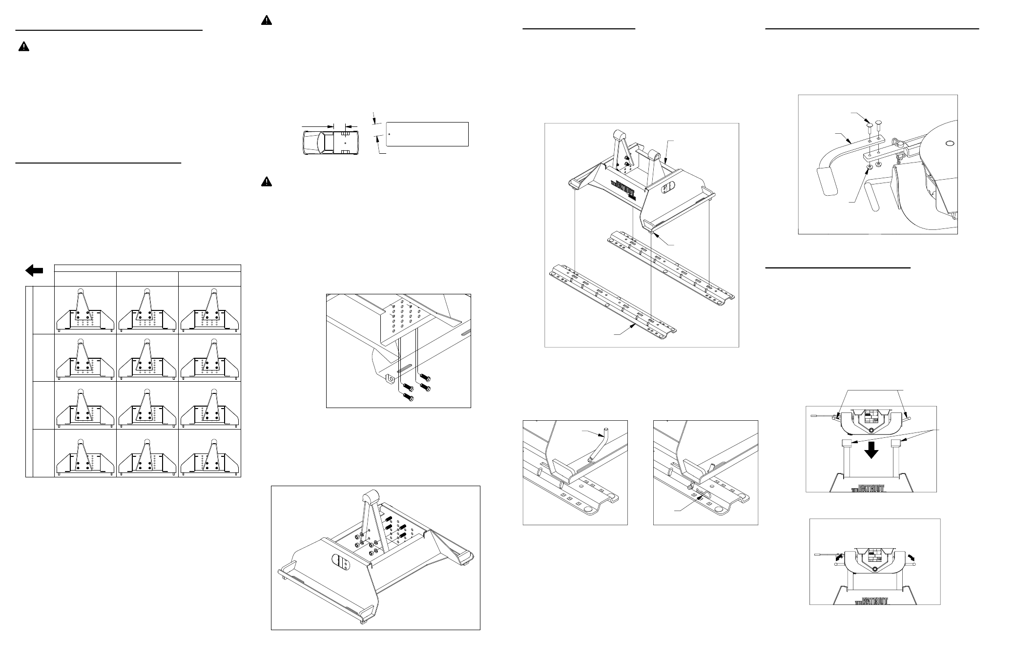
INSTALL BASE
The Patriot 16k base will mount to a universal rail kit
in the truck bed. Remove any debris and/or
obstructions from the bed. Place the Patriot 16k base
over the rail attachment points and carefully lower it
until the pin tabs pass through the attachment points
and the base rests flat against the top of the rails, see
figure B1.
1.
Locate the 4 rail pins and hair pins. Insert each pin
into the long slots in the base and throught the rails.
Lock each pin into place with a hair pin, see figure B2
& B3.
2.
INSTALL COUPLER HANDLE
Locate the two 1/4" x 1" carriage bolts and the two
1/4" nuts provided in a bolt bag. Using the carriage
bolts and the nuts, attach the coupler handle to the
arm and tighten, see figure C1.
INSTALL COUPLER
Lubricate the polyurethane bushings on top of the
pivot arms with high grade lithium grease (available
at your local hardware/automotive store). Pick up the
couper by lifting up on both saddle handles which
will open the saddle latches. Place the coupler over
the pivot arms and allow the saddle latches to fall
back to there original positions. (The saddle handles
should be parallel with the base in the latched
position.) see figure D1 & D2.
FIGURE B1: Rail attachment.
FIGURE B2:
View of base leg.
FIGURE B3:
View of base leg.
FIGURE C1: View of coupler handle.
FIGURE D2: View of coupler and base.
(Saddle handles in locked position)
FIGURE D1: View of coupler and base.
(Saddle Handles up)
PIN TAB
PATRIOT 16k BASE
UNIVERSAL
RAIL KIT
CARRIAGE
BOLTS
NUTS
LATCH
HANDLE
RAIL
PINS
HAIR
PIN
POLYURETHANE
BUSHINGS
SADDLE
HANDLES
PREPARING TO INSTALL
WARNING: Components of the Patriot 16k hitch are
heavy and cumbersome to handle. Failure to use
proper lifting techniques when moving and handling
these parts could result in property damage or
serious injury.
WARNING: B&W also recommends that you check
the clearance between the bed side and the underside
of the front of the trailer and to allow adequate
clearance for the pitch and roll of the trailer while
towing.
WARNING: B&W recommends that you check the
clearance between the truck cab and the trailer.
Compare the measurement taken from the center of
the Coupler to the cab, to the measurement taken
from the center of the king pin to the farthest forward
corner point of the trailer. These measurements will
allow you to see how much clearance you will have
between the cab and the trailer while towing and
turning.
2.
1.
INSTALL PIVOT ARMS
Mount the pivot arms using one of the twelve different
locations illustrated in Table A1. These twelve
locations allow flexibility in coupler height (vertical
adjustment) and distance from the cab (horizontal
adjustment). Choose a location so that your trailer will
be as level as possible and have adequate turning
clearance while towing. See warnings following this
section.
Locate both pivot arms, eight 1/2" cap screws, eight
1/2" split lock washers, and eight 1/2" nuts. Identify
the mounting holes needed to mount the arms in their
optimal location. Pass four 1/2" cap screws through
the bottom of the base into the bolt plate, as shown in
figure A2.
Remove all parts from the packaging and familiarize
yourself with all the parts and tools required. Use the
parts list on the front page to verify that all parts and
hardware are present.
Align the flat side of the pivot arm flat against the bolt
plate while passing the pivot arms over the 1/2" cap
screws. Install four 1/2" Lock washers and 1/2" hex
nuts, as shown in figure A3. After the pivot arms and
bolts are in place, torque each bolt to 80 ft−lbs.
3.
Positions
closest to cab.
2" farther
back from cab.
4" farther
back from cab.
HORIZONTAL ADJUSTMENT
H
ig
he
st
po
si
tio
n
19
"
M
ed
iu
m
po
si
tio
n
18
"
Lo
w
es
t
po
si
tio
n
16
"
M
ed
iu
m
po
si
tio
n
17
"
V
IR
T
IC
A
L
A
D
JU
S
T
M
E
N
T
CAB
TABLE A1
FIGURE: A2: View under base.
FIGURE A3: View looking into base.
CENTER OF
COUPLER
TO CAB
KING PIN TO EDGE OF TRAILER