Final procedures, Ammeter, For all gauges) – Auto Meter 2312 User Manual
Page 4: Model 2318
FOR SERVICE CONTACT: AUTO METER PRODUCTS Inc. 413 W. Elm St., Sycamore, IL 60178 USA (815)899-0801 or
Email us at [email protected]
© 2002 Auto Meter Products, Inc. 2650-560 3/4/02
12 MONTH LIMITeD WARRANTY
The manufacturer warrants to the consumer that this product will be free from defects in materials and workmanship for a period of twelve (12) months from the date of the original purchase. Products
that fail within this 12 month warranty period will be repaired or replaced at the manufacturer’s option to the consumer, when determined by the manufacturer that the product failed because of defects
in material or workmanship. This warranty is limited to the repair or replacement of parts in the instrument and the necessary labor done by the manufacturer to affect the repair or replacement of the
instrument. In no event shall this warranty exceed the original purchase price of the instrument, nor shall the manufacturer be responsible for special, incidental or consequential damages or costs
incurred due to failure of this product. Warranty claims to the manufacturer must be transportation prepaid and accompanied with dated proof of purchase. This warranty applies only to the original
purchaser of product and is non-transferable. All implied warranties shall be limited in duration to the said 12 month warranty period. Breaking the instrument seal, improper use or installation, accident,
water damage, abuse, unauthorized repairs or alterations voids this warranty. The manufacturer disclaims any liability for consequential damages due to breach of any written or implied warranty on all
products made by the manufacturer.
Final Procedures
(For All gauges)
1. Insert light bulb and socket assembly into back of gauge. Connect red
lighting wire to 12V power source in dash lighting circuit. Connect black
wires to good ground, such as dash or chassis ground bolt.
Service
For service send your gauge to Auto Meter in a well packed shipping carton. Please include a note explaining what the problem is, the year and model of your vehicle, engine size,
etc., and your phone number. If you are sending a gauge back for Warranty adjustment, you must include a copy (or original) of your sales receipt from the place of purchase.
NOTE: For light bulb replacement, order Autogage No. 2389
Ammeter
MODeL 2318
Read before installing:
WARNINg:
Have your maximum alternator output tested by an experienced
mechanic. Choice of improper ammeter rating and/or wire size,
and any loose connections can cause dangerous overheating,
which could cause a fire in your vehicle. Ammeter and wire
should have a capacity of at least 10 amps more than your
vehicle’s maximum alternator output.
1. Read instructions thoroughly. The installation of this product requires the
expertise of a trained automotive mechanic. Please consult a qualified
mechanic if you have not had training in the proper installation of an
ammeter.
2. Determine ideal mounting location. Choose a location that will not
obstruct visibility or impair driving movement.
3. Examine your vehicle to determine the best route for wiring to follow.
Choose a path free of hazard of moving parts or hot engine components.
4. Disconnect negative (-) battery cable. (Wear safety glasses.)
5. Hold panel in desired mounting location. Use panel as template and mark
holes to be drilled for mounting.
6. Drill holes with
9
⁄
64
” drill bit and attach panel with screws provided.
7. Auto Meter No. 2228 wire kit must be used for installation. Kits contain a
premium grade wire required for safe installation.
8.
IMPORTANT: Verify that the nuts on both meter terminals are tight.
Follow wiring diagram for car system I or II, and connect ammeter as
illustrated.
CAUTION
DO NOT CONNeCT THe AMMeTeR ACROSS THe BATTeRY.
9.
IMPORTANT:Terminal lugs must be BOTH crimped and soldered to the
wire, and star lockwashers must be used on both sides of the terminal
lugs.
10. Tighten terminal nuts to compress star lockwashers into the terminal lugs.
11. Verify that
none of the ammeter connections are to ground.
12. Secure gauge in mounted panel using non-insulated mounting bracket,
two (2) lockwashers, and two (2) #10 nuts.
13, Snap-in light socket assembly into back of gauge. Connect red lighting
wire to 12V power source in dash lighting circuit. Connect the black wires
to good engine ground (such as body frame bolt).
14. Reconnect negative (-) battery cable.
15. Leaving engine
off, turn on lights. Indicator should read negative (-). If it
reads positive (+), disconnect neg. battery terminal and reverse the wires
on back of meter, then reconnect neg. battery terminal.
Before starting
car, double check that all connections are tight. After starting engine,
check wiring connections for hot spots. Be prepared to shut engine off
immediately if hot spots are detected.
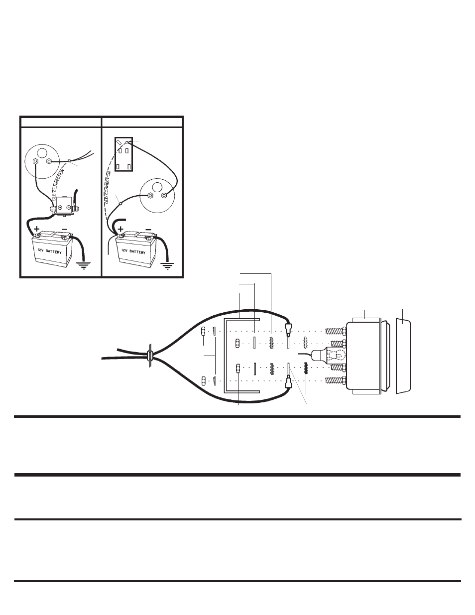
AMMeTeR
Make Ammeter
electrical connections
as illustrated in
Vehicle
System diagram I
or
II above.If neither
diagram matches
your electrical system,
consult your service
manual or qualified
mechanic.
B
A
Rubber
Grommet
in Firewall
Nut
Nut
Split-Lockwasher
To 12V Lighting Circuit
U-Bracket
Star-Lockwasher
Flat-Washer
Star-Lockwasher
Terminal Lug
Steel Panel
Underside
View
Snap-On
Chrome
Bezel
VeHICLe SYSTeM I
AMMeTeR
SOLeNOID
AMMeTeR
JUNCTION BOX
VeHICLe SYSTeM II
To Starter Solenoid
Battery Terminal
To
Starter
Use nut & bolt
to reconnect
electrical system
wires
IMPORTANT
Wrap connection
with elec. tape
Crimp
Connector
(Back
View)
B
B
A
A
2. Reconnect negative (-) battery cable. Re-program your clock and radio if
necessary.