Voltmeter, Oil pressure, vacuum & boost gauges – Auto Meter 2312 User Manual
Page 3
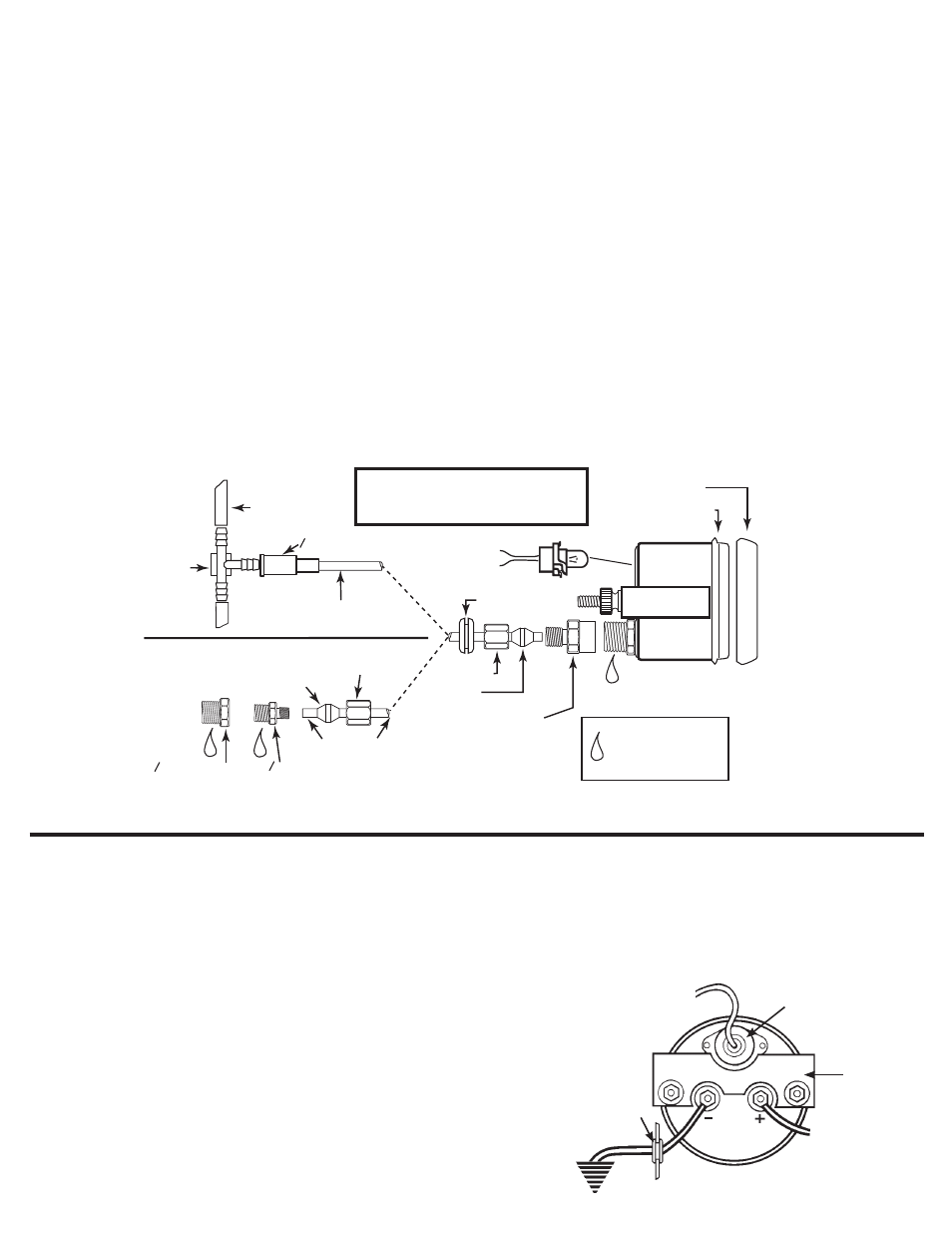
ADAPTeR
USe TeFLON SeALINg
TAPe OR SeALINg
COMPOUND ON
PIPe THReADS
4
"
NPT ADAPTeR
8
"
NPT ADAPTeR
FOR PReSSURe
gAUgeS ONLY
FOR VACUUM
AND BOOST
gAUgeS ONLY
VACUUM HOSe
T-FITTINg
FeRRULe
SeALINg NUT
CONNeCT TO
12V LIgHTINg
CONNeCT TO
gOOD gROUND
gROMMeT
NYLON TUBINg
FeRRULe
SeALINg NUT
8
"
CONNeCTOR
1
NYLON TUBINg
1
1
SNAP-ON
BeZeL
BLACK
BeZeL
U BRACKeT
Voltmeter
MODeL 2319
1. Disconnect the negative (-) battery cable. (Wear safety glasses)
2. Auto Meter wire kit No. 2217 (18-gage) is recommended. Route one length
through firewall using grommet. Attach one end to the left hand terminal (-)
on back of gauge and the opposite end to a good engine ground.
3. Attach one length of wire to the right hand terminal (+) on back of gauge
and opposite end to 12 volt terminal on ignition switch or to any 12 volt
source.
4. Snap-in light socket assembly and connect to dash lighting circuit or to
other 12 volt source. If dash is metal, a ground connection for light is made
when gauge is mounted with brackets provided. If dash is non-metallic (or
if gauge is cup mounted), a separate ground wire must be connected from
gauge case to a good ground.
5. Reconnect negative (-) battery cable.
To 12V Dash
Lighting Circuit
To 12V Terminal
On Ignition
Switch Or Other
12V Source
Ground To
Engine
Light (installed)
U-Bracket
Grommet
Oil Pressure, Vacuum & Boost gauges
1. Gauge can be mounted in 2
5
⁄
8
” dia. dashboard hole in Auto
Meter mounting panels.
2. Drill a
3
⁄
8
” dia. hole and install rubber grommet where pressure
or vacuum line passes through sheet metal, such as firewall.
3. BOOST, OIL PRESSURE, and VACUUM gauges require
attaching nylon pressure line or braided stainless steel
pressure line to port on back of gauge.
For BOOST, connect line to a manifold vacuum/pressure line
using the fittings provided with the gauge and pressure line kits.
For OIL PRESSURE, connect line to the appropriate pressure
port on engine.
For VACUUM, connect line to a manifold vacuum line using the
fittings provided with the gauge and pressure line kits.
4. To help prevent leaks, be sure the end of nylon tubing is cut
cleanly and straight. Slide compression nut onto tubing with
threads toward end of tubing. Next, slide ferrule onto end of
tubing, leaving
3
⁄
16
” between ferrule and end of tubing. Insert
end of tubing into the
1
⁄
8
” NPT male adaptor. Apply pressure
to maintain constant bond between end of tubing and inside
of adaptor. Slide ferrule into the adaptor then compression
nut. Tighten compression nut with
3
⁄
8
” open-end wrench, while
holding adaptor firm with
7
⁄
16
” open-end wrench. This should
form a tight seal between end of tubing and inside of adaptor.
To make sure it is a snug fit, tug lightly on nylon tubing to make
sure it doesn’t come out.
NOTe: Use teflon sealing tape or sealing compound to assure
proper seal on all pipe thread joints (NPTF).
5. Make sure line is free from hazard of moving parts or hot engine
components. Where potential hazard exists, braided stainless
steel pressure line is recommended.
6. Snap in light socket assembly and connect to dash lighting or
other 12 volt light source. If dash is metal, a ground connection
for light is made when gauge is mounted with brackets
provided. If dash is non-metallic (or if gauge is cup mounted), a
separate ground wire must be connected from gauge case stud
to a good ground.
7. Wrap a clean rag around fittings on back of oil pressure gauge
and place a pan on floor under them to protect vehicle interior
from potential oil leaking. Start engine and run for 30 seconds.
Shut engine off and check rag or leaks If none appear, start
engine again and visually check all connections for leaks.
MODeLS 2310, 2312, 2317
NOTe: NYLON PRESSURE TUBING
MUST PROTRUDE OUT FERRULE
END. (APPROx.
1
⁄
16
” TO
3
⁄
16
”