Fuel level, Fuel pressure installation, Gauge specifications – Auto Meter 2312 User Manual
Page 2
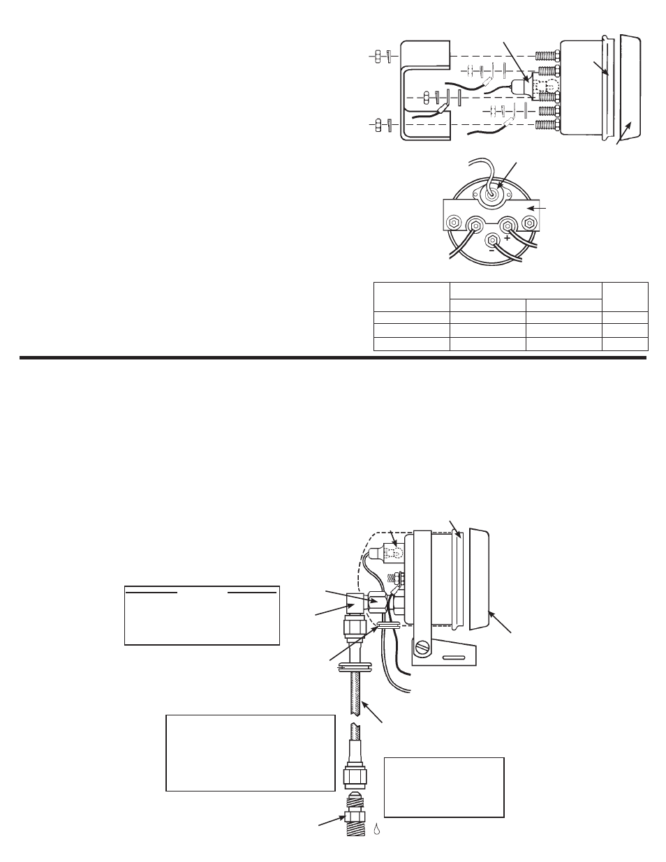
Fuel Level
gauge Specifications
MODeLS 2315, 2316, & 2320
NOTE: For the following installation
THe gAS TANK MUST Be FULL!
1. Disconnect negative (-) battery cable. (Wear safety glasses)
2. Gauge uses vehicle’s stock sender in fuel tank. Existing wires may be
used or route proper length of 18-gage, 2 conductor wire from fuel tank
to gauge. Connect one end to terminal post on fuel level sender and the
opposite end to the sender terminal post (S) on back of gauge. See
figure.
3. Connect wire from negative (-) terminal post on back of gauge to ground
on fuel tank.
4. Connect wire from ignition switch to the positive (+) terminal post on back
of gauge. See figure on right. CAUTION: Be careful not to touch ignition
wire to the sender terminal (S). This will damage the sender.
5. Snap-in light socket assembly and connect to dash lighting circuit or to
other 12 volt light source. If dash is metal, a ground connection for light
is made when gauge is mounted with brackets provided. If dash is non-
metallic (or if gauge is cup mounted), a separate ground wire must be
connected from gauge case stud to a good ground.
6. Reconnect negative (-) battery cable and check reading.
This gauge is designed to operate with the original sender in the vehicle’s fuel
tank. To insure accurate gauge readings, it is important to measure the
resistance (ohms) of the sender with an ohmmeter at full and empty tank
conditions. Consult table for proper gauge application for your vehicle.
NOTE: Production tolerances in the resistance of some vehicle’s tank
senders may cause the gauge to read incorrectly when tank is full.
APPLICATION
SeNDeR ReSISTANCe (OHMS)
gauge
Model No.
FORD/CHRY.
8 to 12
73
2315
GM
90
0
2316
No. 3262 sender
33
240
2320
EMPTY
FULL
U-Bracket
Light (installed)
Black
Bezel
Snap-On
Chrome
Bezel
To 12V Dash
Lighting Circuit
Connect To
Terminal Post
On Stock Sender
In Fuel Tank
Light (installed)
U-Bracket
To 12V Ignition Switch
Ground To Fuel Tank
S
Fuel Pressure
Installation
Ground Wire
Connected to Stud
Snap-On
Chrome
Bezel
Black Bezel
Adaptor
Adaptor
Right
Angle
Fitting
Rubber Grommets
Light
(Installed)
To 12V Dash
Lighting Circuit
3227 3 Foot Stainless
Steel Pressure Line
MODeL 2311
DO NOT USE
NYLON TUBING OR
COMPRESSION
FITTINGS.
FOR FUEL PRESSURE IT IS
STRONGLY RECOMMENDED
THAT BRAIDED STAINLESS
STEEL PRESSURE LINE IS
USED. AUTO METER NO. 3227.
IMPORTANT: The 2311 Fuel Pressure gauge must be mounted outside
of the vehicle’s interior, such as on the cowling in front of the
windshield. This is required to prevent the possibility of fire or
explosion in vehicle interior.
1. Determine best location for mounting the Fuel Pressure gauge on
vehicle’s exterior. Mounting cup kits are available for mounting gauges
on vehicle’s cowling in front of windshield. Drill necessary hole and install
rubber grommet where pressure line passes through sheet metal.
2. Braided stainless steel tubing is recommended because of the highly
flammable nature of racing fuel. DO NOT USE NYLON OR COPPER
TUBING WITH COMPRESSION FITTINGS.
Use Teflon Sealing Tape Or Sealing
Compound On Pipe Threads.
NOTe: This gauge must be mounted
outside of vehicle to prevent possibility
of dangerous explosion of gas fumes
in vehicle interior.
WARNING
3. Route pressure line through grommet to engine
compartment, keeping line free from hot engine
components or moving parts. Plumb line into vehicle’s fuel
line. Be sure to use teflon sealing tape or compound on all
tapered threads for a good seal.
4. Start engine and thoroughly check for any leaks.
5. Snap-in light socket and connect wire to dash lighting
circuit or to other 12 volt source. A separate ground wire
should be attached to gauge case stud and to ground.