Warning, Before you begin – AMMCO 7700 Drum and Disc Brake lathe User Manual
Page 5
AMMCO Drum & Disc Brake Lathes • 1
Before You Begin
Receiving
The shipment should be thoroughly inspected as
soon as it is received. The signed bill of lading is
acknowledgement by the carrier of receipt in good con-
dition of shipment covered by our invoice.
If any of the goods called for on this bill of lading are
shorted or damaged, do not accept them until the car-
rier makes a notation on the freight bill of the shorted
or damaged goods. Do this for your own protection.
NOTIFY THE CARRIER AT ONCE if any hidden loss or
damage is discovered after receipt and request the car-
rier to make an inspection. If the carrier will not do so,
prepare a signed statement to the effect that you have
notified the carrier (on a specific date) and that the car-
rier has failed to comply with your request.
IT IS DIFFICULT TO COLLECT FOR LOSS OR DAM-
AGE AFTER YOU HAVE GIVEN THE CARRIER A
CLEAR RECEIPT.
File your claim with the carrier promptly. Support your
claim with copies of the bill of lading, freight bill,
invoice, and photographs, if available.
Although AMMCO’ s responsibility ceases upon
delivery of the shipment to the carrier, we will gladly
assist in tracing lost shipments. Our willingness to
assist in every possible manner does not make
AMMCO responsible for collection of claims or
replacement of lost or damaged materials. Shipping
damage claims will not be handled under warranty.
Electrical Requirements
The lathe must be properly grounded to protect the
operator from shock. The lathe is equipped with an
approved 3-conductor cord and a 3-prong grounding
type plug to fit the proper grounding-type receptacle.
Should an extension cord be required, use 3-conductor
cords with 3-prong grounding plug and 3-prong ground-
ing receptacle properly rated to handle this electrical
power tool only. Do not modify a cord or plug to match
a receptacle; have a qualified electrician install an
appropriate outlet to match the lathe requirements.
Repair or replace any worn or damaged power cords
immediately.
Verify that the lathe plug and grounding-type recepta-
cle match as shown in Figure 1.
Figure 1 - Power Cord Plug and Receptacle Types
Installation
1.
Assemble bench according to the instructions pro-
vided. Tighten all fasteners securely.
2.
After assembly, the bench should be leveled and
may be bolted down with 3/8 or 7/16 inch bolts or lag
screws.
3.
Unbolt the lathe from the shipping pallet. Lift the
lathe onto the bench.
4.
Bolt the lathe to the bench with the hardware pro-
vided. Tighten fasteners securely.
5.
Remove any packing materials and protective
wrapping from the lathe and components.
6.
Make sure lathe is turned off. Plug lathe into a
properly installed and grounded outlet that matches the
lathe plug.
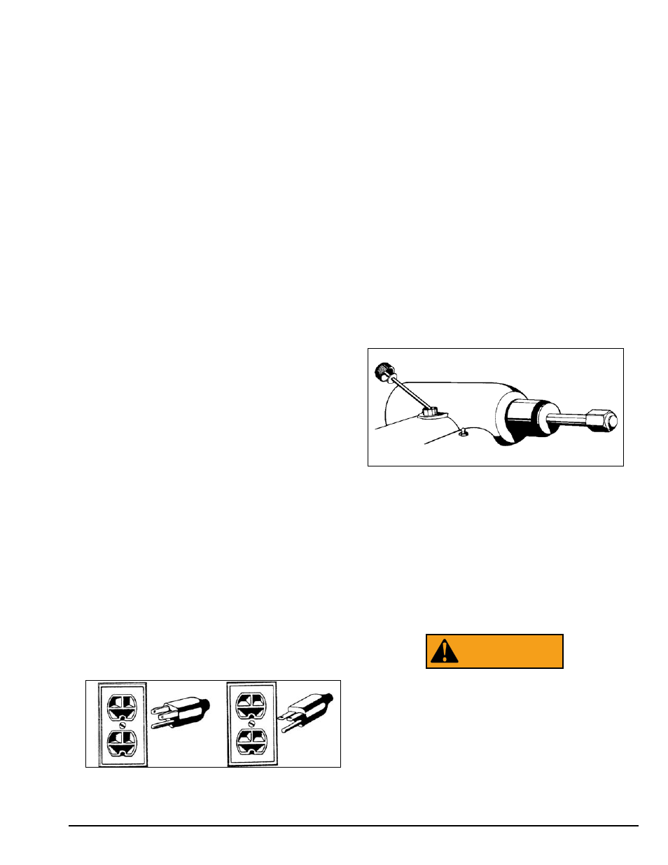
7
. Remove the shipping plug, insert the oil dipstick,
and check oil level. The lathe is shipped with the cor-
rect amount and type of oil. Add oil as necessary to
reach the correct mark on the dipstick. Use only EP-80-
90 gear oil. Oil level should be checked often.
Figure 2 – Check oil level
8.
Clear the area and turn lathe on. Check for proper
operation (motor and spindle rotation).
Preparation for Use
1
. Inspect all adapters and accessories for burrs,
nicks, or other damage.
2.
Clean accessories with a vaporizing solvent.
3.
Apply a light film of oil to all adapters to protect
their machined surfaces from rust. Refer to the main-
tenance section for more information.
There is a circuit breaker located on the elec-
trical panel to prevent damage to the lathe
in the event the motor is overloaded. Move
the switch to the off position and correct
overloading situation before re-setting cir-
cuit breaker. Serious personnal injury could
result if circuit breaker is re-set while lathe is
still on.
WARNING
115 VAC
230 VAC