Reconditioning disc brake rotors – AMMCO 7700 Drum and Disc Brake lathe User Manual
Page 12
8 • AMMCO Drum & Disc Brake Lathes
Figure 16 – Lock cross feed
20.
Set the spindle feed speed while the lathe is run-
ning by unlocking the feed dial lock screw and turning
the dial. Tighten the lock screw when speed is set.
The rough cut feed range is between 0.006” (0.15
mm) (6 on the dial) to 0.020” (0.50 mm) (20 on the
dial).
The finish cut feed range is between 0.002” (0.05
mm) (2 on the dial) and 0.006” (0.15 mm) (6 on the
dial).
21.
Set the feed shut-off by sliding it on the shaft to
a point that approximately equals the depth of the drum
and tightening it in place. The feed will stop when it
reaches this point.
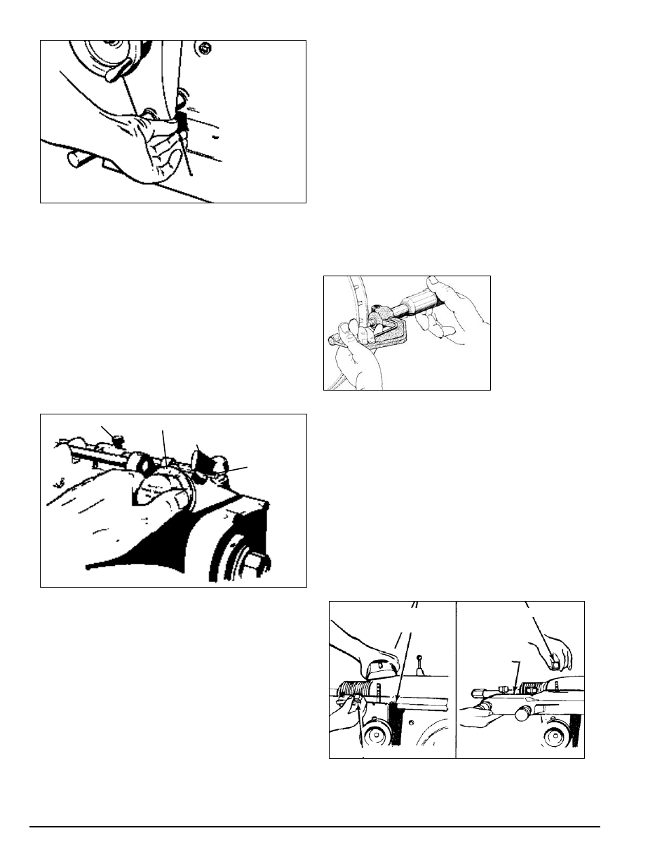
Figure 17 – Set spindle feed shut-off
22.
Engage the feed lever to begin drum recondi-
tioning.
Reconditioning Disc Brake
Rotors
Preparation
1.
Inspect the rotor carefully for scoring, rust ridges
(at the inner and outer circumference of the rotor), and
hard spots. Any excessive wear or deformity should be
noted and, if not within acceptable limits, the rotor
should be replaced.
2.
Use a micrometer to check the thickness of the
rotor at no less than 3 points around the circumference
about 1” (2.54 mm) in from the outer diameter.
If the rotor thickness varies between readings, it
should be reconditioned. However, if the thickness is
less than the minimum established by the manufac-
turer, or if it will be less after reconditioning, the rotor
should be replaced.
Note: Most often
the DISCARD thick-
ness dimension is
cast or stamped
into the rotor, not
the minimum
machine-to thick-
ness.
Figure 18 – Measure rotor thickness
Twin Cutters
A twin cutter tool is used on the 4000, 4100, and
7500 to recondition both surfaces of a brake rotor at
the same time. The twin cutter replaces the boring bar
on top of the cross feed after removing the upper and
lower tool bar clamps.
Model 6950 Twin Cutter—4000 & 7500
1.
Mount the twin cutter on the cross feed with the
stud bolt extending through the cast slot. The slot
helps center the twin cutter to the rotor.
2.
Secure the twin cutter to the cross feed with self-
aligning nut and washer assembly. Tighten the nut
firmly.
Figure 19 – Install the twin cutter
Cross slide self-aligning nut/washer
Twin cutter
Cross slide self-aligning nut/washer
Upper and lower
boring bar clamps
Cross Feed Lock
Knob
Feed shut-off
Spindle feed lever
Spindle feed dial
Feed dial
lock screw