IOGear GCS1004 User Manual
Page 7
7
CPU 3 / 4
CPU 1 / 2
1
2
3
4
4-Port USB
DVI
KVM Switch
GCS1004
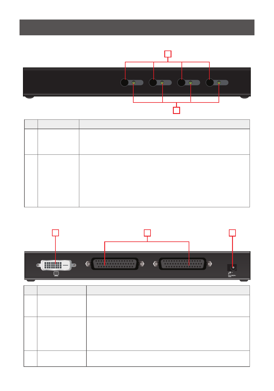
GCS1004 Front View
2
1
1
2
3
GCS1004 Back View
No Component
Description
1
Port Selection
Pushbuttons
For manual port selection, press a port selection pushbutton to bring
the KVM focus to the computer attached to is corresponding port.
See Manual Port Switching, page 10 for more details.
2
Port LEDs
The Port LEDs are built into the Port Selection Switches.
• Flashes indicate that the computer attached to the
corresponding port has the KVM focus and is being accessed in
Auto Scan Mode (see Auto Scanning, page 12).
• Lights steady to indicate that the computer attached to its
corresponding port is the one that has the KVM focus.
• The LED is off when the port is not selected.
No Component
Description
1
DVI Console Port
The cable from your DVI monitor plugs in here.
Note: The USB keyboard and USB mouse ports are located on the
unit’s side panel.
2
Computer Port(s):
The cable(s) that link the switch to your computers plug in here.
Note: You can identify the computers by the port they are con-
nected to – they are labeled CPU1 / CPU2 for GCS1002; CPU1 /
CPU2 / CPU3 / CPU4 for GCS1004.
3
Power Jack
(GCS1004 only)
The power adapter cable plugs into this power jack.