IOGear GCN1000 User Manual
Page 7
7
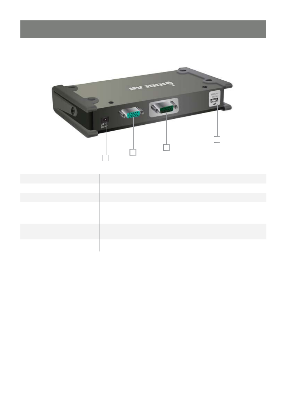
PCI Interface
1
2
3
4
No.
Component
Description
1
Power Jack
The power adapter connection.
2
PC/KVM Port
The connection for the cable that links the GCN1000 to your computer.
3
USB Console Port
This is the connection for the local console cable (USB keyboard,
monitor, and USB mouse). Each port is color coded and marked
with an appropriate icon for identifi cation. *
4
Virtual Media Port
The connection for the virtual media cable that connects the GCN1000
to a USB port on your computer. It allows fi le transfers to occur
5
LAN Port
The network’s Ethernet cable
connection
* Note: if you are using a wireless keyboard/mouse set, connect the receiver to the Keyboard port of the
KVM cable
See also other documents in the category IOGear Computer Accessories:
- GUWA200 (30 pages)
- GCS1804 (56 pages)
- GCS1804 (56 pages)
- GCS634U-PLUS (22 pages)
- GCS1782 (44 pages)
- GUWH104KIT (38 pages)
- GCS1794 (40 pages)
- GUB211W6 (30 pages)
- GCS12 (18 pages)
- GCS12 (34 pages)
- GCS932UB (32 pages)
- GCS1734 (44 pages)
- GCS124U (32 pages)
- GCS82B Manual (28 pages)
- GCS1762 (45 pages)
- GCS1764 (46 pages)
- GCS602 (22 pages)
- GCS1758 (54 pages)
- GCS138KIT (33 pages)
- GCS1714 (32 pages)
- MINIVIEW GCS1774 (3 pages)
- GUIP204 v1 (56 pages)
- GCS1744 (48 pages)
- GCS661U (36 pages)
- GCS661UW6 (32 pages)
- GCS1774 (45 pages)
- GUH284R (17 pages)
- GHPB42W6 (75 pages)
- GCS82B/GCS84B (29 pages)
- GUWH204KIT (40 pages)
- GCS614A Manual (26 pages)
- MINIVIEW GCS52U (24 pages)
- GBU221P (60 pages)
- GBC201 (45 pages)
- GBGPS201 (51 pages)
- GBGPS201 (118 pages)
- GBGPS201 (21 pages)
- GBHFK211W6 (1 page)
- GBHFK231W6 (36 pages)
- GBHFK331 (36 pages)
- GBMH201 (32 pages)
- GBMA211W6 (1 page)
- GBMH221 (1 page)
- GBP201 (26 pages)
- GBP301 (40 pages)