2 load cell calibration procedure, Load cell calibration procedure -8, Platform support torque values -8 – JLG M600 Service Manual User Manual
Page 118
SECTION 4 - BOOM & PLATFORM
4-8
– JLG Lift –
3121813
4.2 LOAD CELL CALIBRATION PROCEDURE
1. Place the machine in the stowed position.
2. Activate both emergency stop switches and turn the
key switch to the platform position.
3. Remove all loads from the basket including the
operator.
4. Turn P1 clockwise (in) until the potentiometer begins
to click.
5. Plug the analyzer into the port in the platform.
6. Enter the password 33271.
7. Select Machine Set-Up/Load Cell/ 1=Warn Only.
8. Select Diagnostics/System/Load Cell on the Ana-
lyzer.
9. Adjust P2 until the load = 0%.
10. Place 455 lbs. in the center of the basket.
11. Adjust P1 until the load = 100%.
12. Verify that the overload lamp lights continuously and
the alarm sounds continuously during an overload
condition.
13. Remove the weight from the basket.
14. Adjust P2 until the load = 0%.
15. Place 500 lbs. (230kg) in the center of the basket.
16. Adjust P1 until the load = 95%.
17. Add 55lbs. (25kg) in center of the basket.
18. Verify that the overload lamp lights continuously and
the alarm sounds continuously during an overload
condition.
19. Remove weight from the basket.
20. Seal Potentiometers with fingernail polish.
21. When an overload condition is reached, the
machine will give an indication by activating the tilt
alarm, lighting the overload light, put all platform
functions into creep, cutout lift up and telescope out
at platform and ground.
The horn will be activated when MTB ground control
switch is selected to ground and overload condition
is reached.
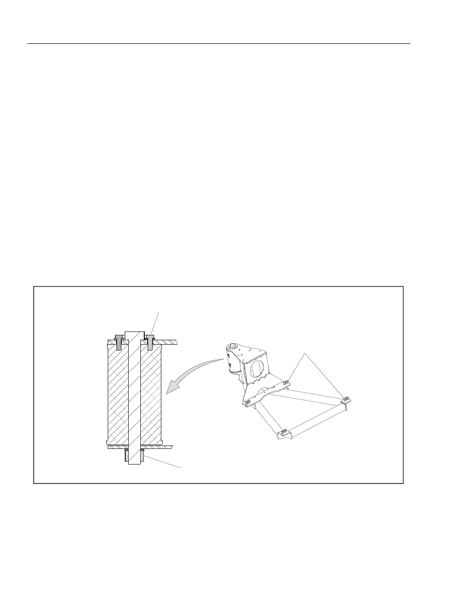
A,B,D
C,D
E
A
B
C
D
E
Torque to 50 ft.lbs. (68 Nm)
Loctite #242
Torque to 480 ft. lbs. (650 Nm)
Check torque every 150 hours of operation
Torque to 85 ft. lbs. (115 Nm)
Figure 4-6. Platform Support Torque Values
NOTE: If any rotator bolts are replaced, all bolts
on the rotator should be retorqued.