Pump-motor assembly - remove/install, Motor assembly - remove/install - reference marks – JLG 10MSP Service Manual User Manual
Page 54
SECTION 3 - BASE COMPONENTS
3-22
– JLG Lift –
3121228
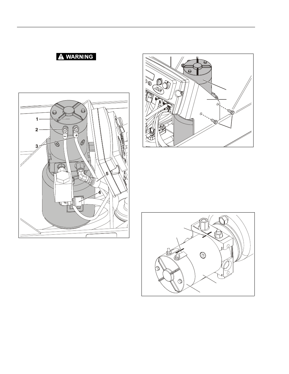
Pump-Motor Assembly - Remove/Install
BE CERTAIN THE MAST IS FULLY LOWERED BEFORE REMOV-
ING ANY HYDRAULIC LINES FROM THE PUMP UNIT. WEAR PRO-
TECTIVE GEAR WHEN WORKING AROUND PRESSURIZED
HYDRAULIC LINES. REMOVE CONNECTIONS CAREFULLY AND
CAP ALL LINES AND PORTS WHEN DISCONNECTED.
Pump-Motor Assembly - Remove/Install
Motor Assembly - Remove/Install - Reference
Marks
Hydraulic Pump Assembly Components
1. Hydraulic Pump/Motor/
Reservoir Assembly
2. (–) Power Cable from
Ground Control Station (a)
3. (+) Power Cable from Grou
nd Control Station (a)
4. Hydraulic Extend Pres-
sure Line to Lift Cylinder
(b)
5. Hydraulic Return Line
from Lift Cylinder (b)
NOTE: (a) Shown with protective cover removed.
(b) Completely lower platform before loosening any
hydraulic lines to remove any pressure remaining in the
lines. Take proper caution and wear protective gear
anytime you are opening a hydraulic line.
Once power cables and hydraulic lines are removed
from this side of pump assembly, remove the mounting
screws from the other side of the pump, see the follow-
ing illustration.
Hydraulic Pump Mount and Mounting Screws
1. Hydraulic Pump/Motor/
Reservoir Assembly
2. Pump/Ground Control Sta-
tion Mounting Bracket
3. Pump Mounting
Screws (a)
NOTE: (a) Apply Loctite #242 to screw threads before final
assembly.
Pump Motor - Removal/Installation - Reference Marks
• For reference when reassembling, mark motor cover, housing
and valve body position before disassembling.
1. Motor Top Cover
4. Housing/Motor Valve Body
2. Cover/Housing
Reference Mark
Reference Mark
5. Motor Valve Body
3. Motor Housing
1
2
3
3
4
1
2