Code 04 - tilt condition, Code 05 - reserved, Code 06 - drive motor brush wear warning indicator – JLG 10MSP Service Manual User Manual
Page 123: Code 07- left drive motor - disconnected, Code 04 - tilt condition -19, Code 07 - left drive motor - disconnected -19, See table 6-7, Ge 6-19, See table 6-8, 19 code 05 - reserved
SECTION 6 - TROUBLESHOOTING
3121228
– JLG Lift –
6-19
Code 04 - Tilt Condition
Check For These Obvious Conditions First:
• If machine is on a tilt of more than 1.5° in either or both the X or Y direction, this is normal operation.
(DRIVE and LIFT UP are disabled when tilt is detected)
• Check if Ground Control Module is mounted securely to the mast support column.
Code 05 - RESERVED
Code 06 - Drive Motor Brush Wear Warning Indicator
• Replace Drive Motor Brushes - see Section 3.5, Wheel Drive Assembly - Servicing - for brush replacement instructions.
• Program Ground Control Station module to reset the Brush Wear Warning Timer - see Section 4.4, Ground Control Mod-
Code 07- Left Drive Motor - Disconnected
Check For These Obvious Conditions First:
• Check left drive motor M1 connector at the Traction Control Module for secure and proper connection.
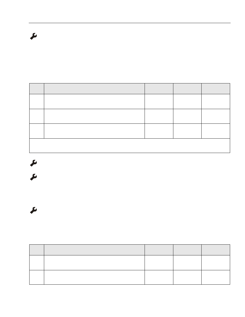
Table 6-7. Code 04 - Tilt Condition
STEP
ACTION
SPEC
YES
NO
1.
Using a digital level check the actual level of the machines’ resting surface in
both the X and the Y directions. Does surface check within machine specifi-
cation.
1.5°
X and Y Direction
Go to Step 2
Drive Machine to
Level Surface
2.
At the Ground Control Module, enter the programming mode (See Ground
Control Programming, Section-3 of Service Manual) and check the tilt sen-
sor X and Y readings. Are readings within machine specification?
1.5°
X and Y Direction
Replace Ground
Control Module
Go to Step 3
3.
Zero Tilt Sensor on a surface checked to within 0.0 degrees with a digital
level in both the X and Y directions. (See Ground Control Programming, Sec-
tion-3 of Service Manual).
—
—
—
NOTE: If frequent calibration of the internal Tilt Sensor is required, replace the Ground Control Module.
Table 6-8. Code 07 - Left Drive Motor - Disconnected
STEP
ACTION
SPEC
YES
NO
1.
Check resistance across positive (+) and negative (–) drive motor leads in
M1 connector wiring harness going to the left drive motor. Is reading within
spec?
.1 to .3 ohms
Replace Traction
Module
Go to Step 2
2.
Repair or replace left drive motor wiring, brushes or motor.
(For brush replacement, see Section 3 of this Service Manual)
—
—
—