Motor, brake and gear box assembly, Motor, brake and gear box assembly -19 – JLG 10MSP Service Manual User Manual
Page 51
SECTION 3 - BASE COMPONENTS
3121228
– JLG Lift –
3-19
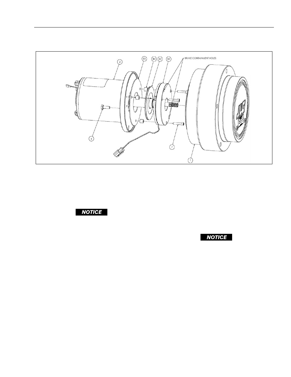
Motor, Brake and Gear Box Assembly
1. Place the Motor (2) shaft up on the bench.
2. Place the Brake Friction Plate (B3) onto face of the
motor flange. Line up the three holes of the Brake
Friction Plate (B3) with the tapped holes in the
motor flange.
WHEN MOUNTING THE BRAKE FRICTION PLATE TO THE MOTOR
FLANGE, CHECK THAT THE MOTOR HOUSING TO FLANGE
MOUNTING BOLTS ARE NOT CONTACTING THE BRAKE FRIC-
TION PLATE UNDERNEATH. CONTACT INTERFERENCE COULD
CAUSE THE BRAKE FRICTION PLATE TO WARP WHEN TIGHT-
ENED DOWN.
3. Place the Brake Disc (B2) on the motor shaft. Make
sure the splines are properly lined up and the Brake
Disc (B2) is down against the Brake Friction Plate
(B3).
4. Place the three Spacers (B4) so that they line up
with the three holes in the Brake Friction Plate
(B3).
5. Carefully place the Brake Housing (B1) onto the
Spacers (B4) so that the holes in the Brake Hous-
ing (B1) line up with the holes in the Spacers (B4).
Make sure that the wire leads coming out of the
Brake Housing (B1) are lined up with the slot in the
motor flange.
6. Install the three Brake Bolts (7) into the three holes
in the Brake Housing (B1). Tighten to 4-5 ft-lbs.
7. Remove and discard the 2 bolts in the Brake Con-
tainment Holes.
8. Pull the Brake Lead through the slot in the motor
flange. Make sure the leads are all the way in the
bottom of the slot.
9. Install a wire tie around the brake leads and the
motor housing. Position the wire tie so that it is
approximately 2" back from the motor flange.
10. If the Gearbox (1) is loose from the machine place it
onto the bench with the cover side down. If the
Gearbox (1) is attached to the machine, perform the
next step with extreme caution.
BEFORE MOUNTING THE DRIVE MOTOR/BRAKE ASSEMBLY TO
THE GEARBOX SPINDLE HUB BE CERTAIN THE BRAKE CAVITY
INSIDE THE GEARBOX IS CLEAN AND FREE OF ANY OIL RESI-
DUE.
11. Slowly slide the Motor (2) into the Gearbox (1).
Make sure that the end of the motor shaft does not
damage the Gearbox (1) lip seal.
NOTE: The motor may need to be rotated to line up the sun gear
splines with the motor shaft splines.
12. Install the 2 Motor Bolts (6). Tighten to 8-9 ft-lbs.
13. Apply a bead of silicone sealant to the slot in the
motor flange where the brake leads are exiting.
14. Fill the Gearbox (1) with oil per instructions (See
15. The wheel drive is now ready to be installed onto the
machine, reverse removal instructions (See Page 3-
6).
Motor, Brake and Gear Box Assembly