Daily rear axle lock-out test procedure, P7.0 – JLG TF6-42 (9150-4003) Operator Manual User Manual
Page 82
DAILY REAR AXLE LOCK-OUT TEST PROCEDURE
TESTING REAR AXLE LOCKING SYSTEM (perform daily test)
The TF6-42 is equipped with a rear axle locking system for use while in work
platform mode. In this mode, when the boom is raised above 50 degrees, a
cylinder at the rear will lock, preventing oscillation of the rear axle. With the
boom below this angle the cylinder will allow the rear axle to oscillate freely.
When the machine is in material handler mode, the rear axle cannot be locked,
the rear axle will always oscillate freely.
After attaching the work platform and connecting the electrical cables, the
work platform mode should be checked to ensure proper operation of the rear
axle stabilization locking system.
Checking the rear axle locking system in work platform mode
Perform the following check from the work platform. No material, equipment,
or personnel other than the operator should be on the platform during the
performance of this test. This test will require the use of an assistant on the
ground.
1.)
Position Control Station Selector Key switch to Platform.
2.)
Start the machine from the platform. Raise the boom to approximately
zero degrees (horizontal) boom angle.
3.)
Locate an eight inch curb, and drive the machine’s left front wheel up
on the curb, leaving all other wheels off the curb.
4.)
Level the machine by operating the Sway function. No wheel should
leave the ground.
5.)
Back the left front wheel off the curb. Again, no wheel should leave the
ground.
6.)
Drive the left front wheel back up on the curb, and release the drive
controller. Use the sway function to level the machine.
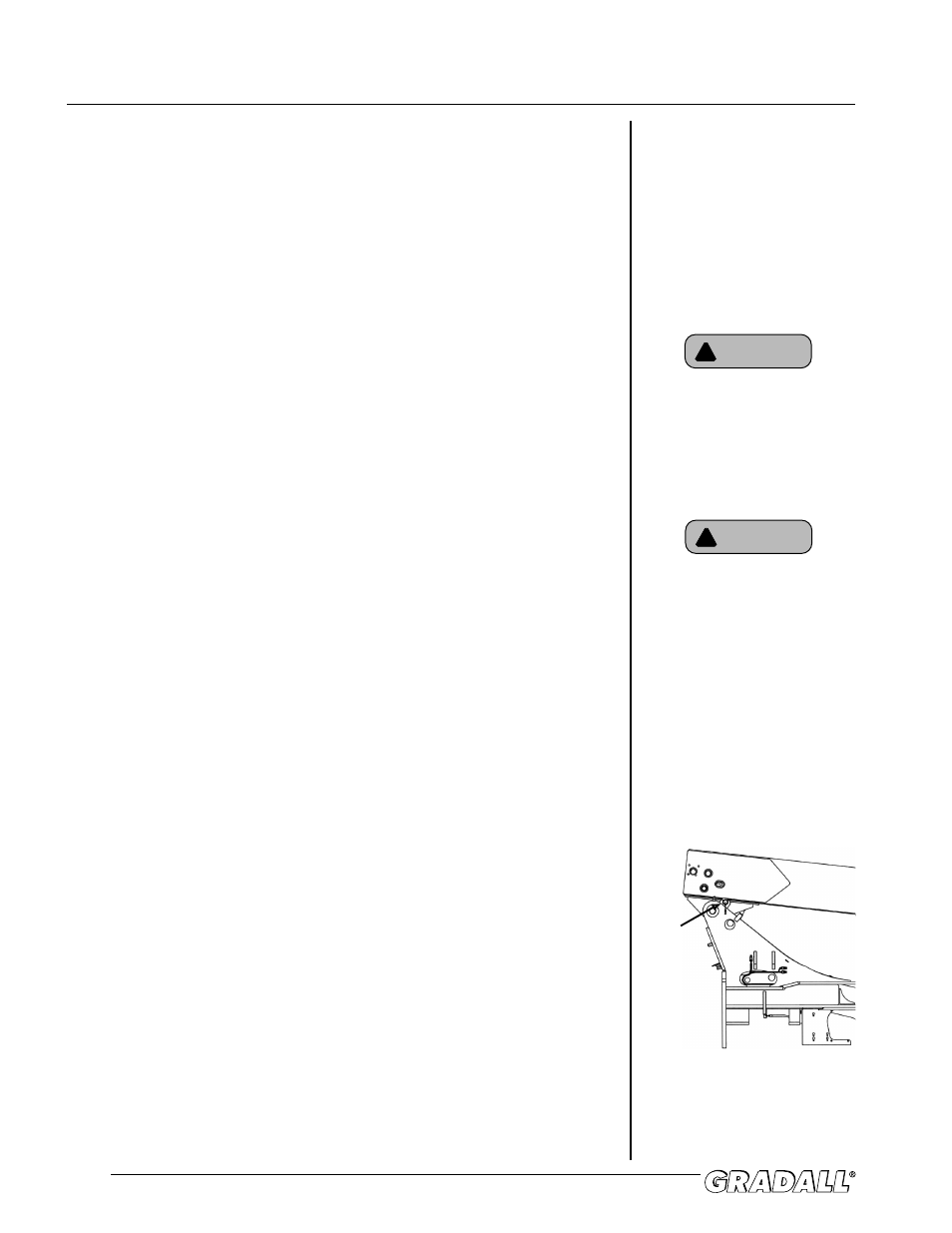
7.)
While keeping clear of the rear wheels, have an assistant check that
the red LED on the proximity switch at the right rear of the machine
is “glowing”. Have the assistant disconnect the proximity switch from
the wire harness. The red LED should be “OFF” (see figure 7-1).
8.)
Back the left front wheel off the curb. The rear axle should be locked
and one wheel should be off the ground. Set the park brake.
9.)
Again, staying clear of wheels, have the assistant reconnect the
proximity switch to the wire harness. The raised wheel should
immediately return to the ground.
10.)
If the machine has passed all of these checks, place the machine on
level ground, set the park brake and raise the boom above 50 degrees.
11.)
Have the assistant check that the red LED on the proximity switch at
the right rear of the machine is “OFF”.
P7.0
Do not raise boom above 5 degrees
for steps 1 through 9 of this check.
WARNING
!
Should the machine fail any part of
this check, immediately discontinue
the checking process. Do not use
the machine. Place a “DO NOT
OPERATE” tag on the machine, and
have it repaired.
WARNING
!
Figure 7-1
Proximity
Switch
12
12