Decals 2.2, Sample only - use chart in cab, Model tf6-42 – JLG TF6-42 (9150-4003) Operator Manual User Manual
Page 14: Instructions
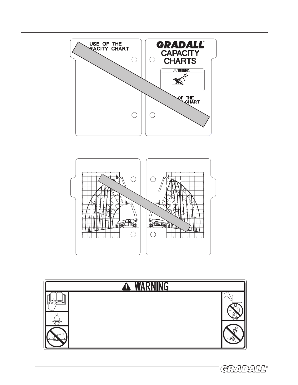
DECALS
2.2
Located on right cab wall
P/N 9150-3098
9150-3098 REV. A
F o r s a f e o p e r a t i o n o f m a c h i n e , a n d t o m i n i m i z e r i s k o f
s e r i o u s i n j u r y, R E A D A N D O B S E RV E t h e f o l l o w i n g :
6. Keep others away from machine when operating. Do not
allow others to stand under boom or load. Always look in
direction of travel.
7. Use extreme care when handling long, high or wide loads.
Do not handle unstable or loosely stacked loads.
8. Forks must be centered under load, and spaced apart as far
as possible.
9. Level machine before lifting any load above 4 feet (1.2m).
10. Improper use of machine could result in machine tipping
over. If machine starts to tip over, do not leave operator's
seat. Lean away from tip, and brace yourself.
11. Keep mirror(s) clean and properly adjusted. Objects in
mirror(s) are closer than they appear.
5. On inclines, travel with load up-grade.
1. Only trained and authorized personnel may operate this
machine.
2. Before operating, read and understand all capacity charts,
operator manual and safety manuals.
3. Operator must be seated with seat belt fastened. Assure all
controls are in neutral before ignition switch is turned on.
4. Do not travel with boom raised. When traveling, fully
retract boom and place forks in carry position, which is
approximately 4 feet (1.2 m) above ground. Tilt carriage
back slightly to cradle load. Use extreme caution when
turning.
BACK
FRONT
RATED CAPACITY @ 2 FT LOAD CENTER
9150-3083 (-)
48" & 72" CARRIAGES
MODEL
TF6-42
USE WITH:
9140-5073 48" CARRIAGE
9140-5074 72" CARRIAGE
9140-5077 72" DRYWALL CARR. (4,000 LB MAX. CAPACITY)
9140-5054 60" 3/4 YD. BUCKET (4,500 LB MAX. CAPACITY)
9140-5055 74" 1 1/4 YD. BUCKET (4,500 LB MAX. CAPACITY)
9140-5071 102" 1 1/4 YD. BUCKET (4,500 LB MAX. CAPACITY)
9150-3083 (-)
MODEL
TF6-42
48" & 72" SLOPE PILER
USE WITH:
9140-5101 48" SLOPE PILER CARRIAGE
9140-5079 72" SLOPE PILER CARRIAGE
6600 LBS
6000 LBS
5000 LBS
4000 LBS
3000 LBS
2000 LBS
1200 LBS
6600 LBS
5000 LBS
4000 LBS
3000 LBS
2000 LBS
800 LBS
RATED CAPACITY @ 2 FT LOAD CENTER
0°
10°
20°
30°
40°
50°
60°
1
2
3
4
5
6
-9°
0'
-4'
-8'
4'
8'
12'
16'
20'
24'
28'
32'
36'
40'
44'
0'
4'
8'
12'
16'
20'
24'
28'
32'
70°
48'
1
2
3
4
5
6
0'
-4'
-8'
4'
8'
12'
16'
20'
24'
28'
32'
36'
40'
44'
0'
4'
8'
12'
16'
20'
24'
28'
32'
48'
70°
60°
50°
40°
30°
20°
10°
0°
-9°
SAMPLE ONLY - USE CHART IN CAB
Located on dashboard
P/N 9150-3083
Located on dashboard
P/N 9151-3207
Instructions
TWO METHODS OF USING THE CAPACITY CHART.
Method 1
1. The operator must determine:
BOOM EXTENSION NUMBER where the load
is to be placed.
BOOM ANGLE where the load is to be
placed.
2. On the capacity chart, find the arc for the boom
extension number, and follow it down to the boom
angle.
3. The number in the load zone where these two cross
is the maximum capacity for this lift. If the two cross
at a division between zones, the smaller number
must be used.
Method 2
1. The operator must determine:
HEIGHT where the load is to be placed.
DISTANCE from the front of the machine
where the load is to be placed.
2. On the capacity chart, find the line for the height and
follow it over to the distance.
3. The number in the load zone where the two cross is
the maximum capacity for this lift. If the two cross
at a division between zones, the smaller number
must be used.
For each method, the number in the load zone must be
equal to or greater than the weight of the load to be
lifted. Determine the limits of the load zone on the
capacity chart by boom angle AND boom extension number.
Keep the load within theses limits.
9151-3207 REV.-
BACK
Instructions
The operator MUST:
1. Make sure the handler is on a firm, level surface
before lifting or placing a load.
2. Make sure that the capacity charts are for the
appropriate Gradall model.
3. Make sure that the Part Numver shown on the
attachment's Serial Number Plate matches the Part
Number shown on the capacity chart.
4. Be sure of the WEIGHT of the load to be lifted.
TIPOVER HAZARD. Failure to comply with
instructions could result in death or serious
injury.
9151-3207 REV.-
R
FRONT
SAMPLE ONLY - USE CHART IN CAB