Understanding rated capacity charts, Rated capacity chart, Elevation – JLG TF6-42 (9150-4003) Operator Manual User Manual
Page 32: Boom extension, Boom angle, Warning, Sample only - use chart in cab, Model tf6-42
13.0
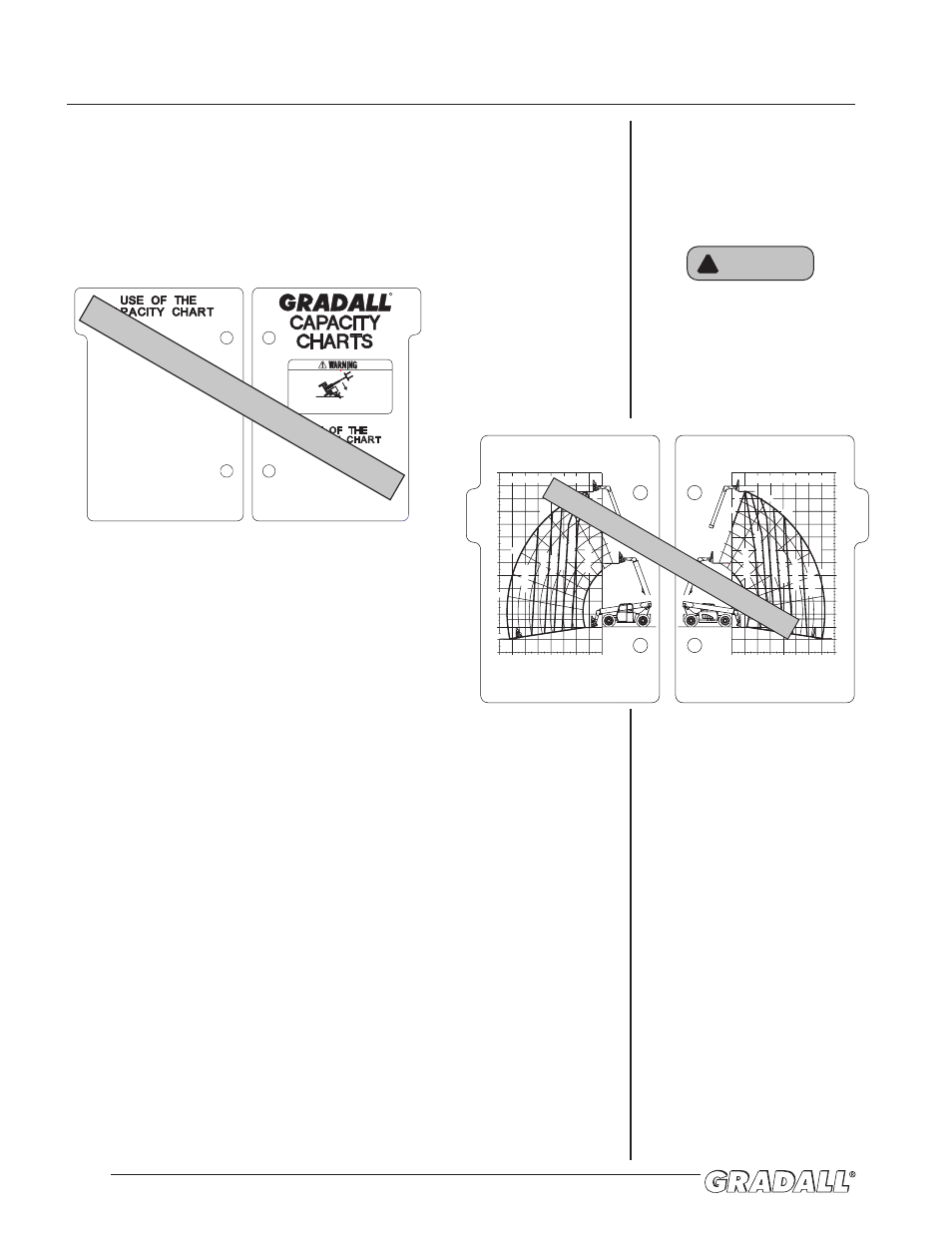
Rated Capacity Chart
The rated capacity chart, located on dashboard, indicates maximum load
capacities for handlers equipped with GRADALL-furnished carriage/fork or other
attachment combinations. These capacities apply to standard carriage/fork and
other attachment combinations except as stated on the capacity chart.
Figure 12-3
Elevation
Numbers at left side of sample chart represent elevation to top of horizontal
fork as measured from level ground (in feet). Elevation relates to dimension “A”
shown on serial number plate inside operator’s cab.
Boom Extension
Numbers across bottom of sample chart and numbers parallel to boom represent
boom reach as measured from front of front tires to extended position.
Number decals on boom relate directly to boom extension. The largest number
which can be read from operator’s seat indicates total boom extension and
must be matched with boom angle to determine load capacity.
Boom extension relates to dimension “D” shown on serial number plate.
Boom Angle
Numbers shown at ends of angled lines represent angle of boom to horizontal
as measured from horizontal. Maximum angles are -9° below horizontal with
boom fully lowered to 70° above horizontal with boom fully raised.
A boom angle indicator is located on left side of boom-section 1 to show boom
angle. Be sure machine is level from front to rear or indicator will provide
incorrect reading.
WARNING
!
All loads shown on rated capacity
chart are based on machine being
on firm, level ground; the forks
being positioned evenly on
carriage; the load being centered
on forks; proper size tires being
properly inflated; and the handler
being in good operating condition.
NOTE!
See page 13-2 for instructions
on how to read capacity charts.
UNDERSTANDING RATED CAPACITY CHARTS
BACK
FRONT
RATED CAPACITY @ 2 FT LOAD CENTER
9150-3083 (-)
48" & 72" CARRIAGES
MODEL
TF6-42
USE WITH:
9140-5073 48" CARRIAGE
9140-5074 72" CARRIAGE
9140-5077 72" DRYWALL CARR. (4,000 LB MAX. CAPACITY)
9140-5054 60" 3/4 YD. BUCKET (4,500 LB MAX. CAPACITY)
9140-5055 74" 1 1/4 YD. BUCKET (4,500 LB MAX. CAPACITY)
9140-5071 102" 1 1/4 YD. BUCKET (4,500 LB MAX. CAPACITY)
9150-3083 (-)
MODEL
TF6-42
48" & 72" SLOPE PILER
USE WITH:
9140-5101 48" SLOPE PILER CARRIAGE
9140-5079 72" SLOPE PILER CARRIAGE
6600 LBS
6000 LBS
5000 LBS
4000 LBS
3000 LBS
2000 LBS
1200 LBS
6600 LBS
5000 LBS
4000 LBS
3000 LBS
2000 LBS
800 LBS
RATED CAPACITY @ 2 FT LOAD CENTER
0°
10°
20°
30°
40°
50°
60°
1
2
3
4
5
6
-9°
0'
-4'
-8'
4'
8'
12'
16'
20'
24'
28'
32'
36'
40'
44'
0'
4'
8'
12'
16'
20'
24'
28'
32'
70°
48'
1
2
3
4
5
6
0'
-4'
-8'
4'
8'
12'
16'
20'
24'
28'
32'
36'
40'
44'
0'
4'
8'
12'
16'
20'
24'
28'
32'
48'
70°
60°
50°
40°
30°
20°
10°
0°
-9°
SAMPLE ONLY - USE CHART IN CAB
Instructions
TWO METHODS OF USING THE CAPACITY CHART.
Method 1
1. The operator must determine:
BOOM EXTENSION NUMBER where the load
is to be placed.
BOOM ANGLE where the load is to be
placed.
2. On the capacity chart, find the arc for the boom
extension number, and follow it down to the boom
angle.
3. The number in the load zone where these two cross
is the maximum capacity for this lift. If the two cross
at a division between zones, the smaller number
must be used.
Method 2
1. The operator must determine:
HEIGHT where the load is to be placed.
DISTANCE from the front of the machine
where the load is to be placed.
2. On the capacity chart, find the line for the height and
follow it over to the distance.
3. The number in the load zone where the two cross is
the maximum capacity for this lift. If the two cross
at a division between zones, the smaller number
must be used.
For each method, the number in the load zone must be
equal to or greater than the weight of the load to be
lifted. Determine the limits of the load zone on the
capacity chart by boom angle AND boom extension number.
Keep the load within theses limits.
9151-3207 REV.-
BACK
Instructions
The operator MUST:
1. Make sure the handler is on a firm, level surface
before lifting or placing a load.
2. Make sure that the capacity charts are for the
appropriate Gradall model.
3. Make sure that the Part Numver shown on the
attachment's Serial Number Plate matches the Part
Number shown on the capacity chart.
4. Be sure of the WEIGHT of the load to be lifted.
TIPOVER HAZARD. Failure to comply with
instructions could result in death or serious
injury.
9151-3207 REV.-
R
FRONT
SAMPLE ONLY - USE CHART IN CAB