Operator’s cab – JLG TF6-42 (9150-4003) Operator Manual User Manual
Page 21
Form No. 20136 3/03 • TF6-42 Owner/Operator Manual
Hourmeter: This meter indicates total time of engine operation in hours
and tenths of hours.
Start/Aux. Switch: The control selector switch must be in cab position for start/
aux. switch to be operational. Momentarily push switch up to start engine. With
engine off, simultaneously push switch down and activate controls to activate
auxiliary power.
Level Indicator: This bubble level indicator enables the operator to
determine the left to right level condition of the handler.
Lights Switch (optional): This switch controls optional lighting which may
be provided with the handler.
Machine Level Lever: This lever controls the relationship of the handler
frame to the front axle. Move the lever left to tilt frame to left, move the
lever right to tilt frame to right.
Microprocessor Controller: This unit processes information for the
transmission.
Neutral Lock Lever: The transmission control lever is equipped with a switch that
locks the transmission control lever in neutral when activated.
Parking Brake Switch: This switch controls the application and release of
the parking brake. Indicator light on switch glows (red) to indicate brake is
applied.
Seat lock Release Lever: This lever unlocks and locks seat position
adjustment.
Service Brake: This pedal operates the service brakes. The further the pedal
is depressed, the slower the travel speed. Full depression of pedal causes full
service brake application.
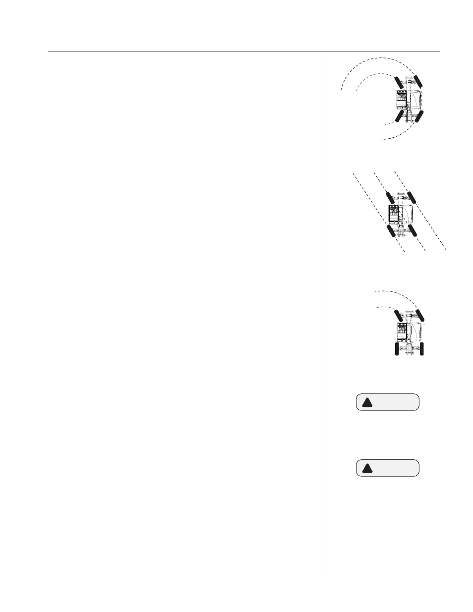
Steer Select Switch: This switch has three positions to allow selection of
4-wheel circle steer, 4-wheel crab steer and 2-wheel steer. 4-wheel circle
steer allows the front and rear wheels to steer in opposite directions for
tight turns. 4-wheel crab steering turns the front and rear tires in the same
direction for moving the machine to the side. 2-wheel steer allows only the
front wheels to steer.
Steering Wheel: The steering wheel controls the angle of wheels. Turning the
steering wheel to the right causes a right turn. Turning the steering wheel to
the left causes a left turn.
Transmission Control: This lever engages forward or reverse travel. Push lever
fully forward for forward travel; pull lever fully backward for reverse travel. Move
lever to centered position for “Neutral.” Twist hand grip to select gear.
Transmission Temperature Light: This light will illuminate during starting
procedure for a bulb check. If transmission temperature exceeds 250° light
will glow indicating the need for service.
Voltmeter: This gauge indicates alternator output and battery condition.
3.2
When traveling at higher speeds
use 2-wheel front steering.
CAUTION
!
4-Wheel Circle Steer
4-Wheel Crab Steer
2-Wheel Front Steer
If transmission temperature light
glows, move material handler to
a safe location and shut down.
CAUTION
!
OPERATOR’S CAB