Understanding rated capacity charts, How to read a capacity chart – JLG TF6-42 (9150-4003) Operator Manual User Manual
Page 34
13.2
How to read a Capacity Chart
When reading the capacity chart you must check to be sure the correct model
number is listed (see figure 12-6). The next thing to look for is that the part
number of your attachment is listed under the “Use With” section.
Identify and find the amount of boom extension required, along with the
angle of the boom. Trace the boom extension arc down until it intersects
with the appropriate boom angle. If the intersection of the boom extension
arc and the boom angle line occur within a weight region, the value within
that region is the maximum capacity for that particular lift. If the intersection
occurs on a bold line separating capacity regions, the smaller of the two
values must be used. The regions are clearly marked with heavier outlines
as shown on page 12.4. If you do not have the correct capacity chart for
your machine and/or attachment, contact your Distributor or Gradall to order
one.
Example (this is for instructional purpose only - use capacity chart
located in your cab):
A contractor has purchased a TF6-42 with the 48” Slope Piler Carriage
Attachment (see figure 12-6). He knows his attachment may be used with
this model since the attachment part number, 9140-5101, matches the
attachment part number stamped on the machine Serial Number Plate. He
also knows that the Capacity Chart is correct since it is clearly marked for
use with a TF6-42 and that the attachment he is using is listed at the bottom
by part number. He has determined the weight of the load to be lifted is 400
lbs. and that he needs to place the load at a boom extension of 6 at a boom
angle of 20°. By tracing the boom extension arc down to where the 20° line
intersects it, the contractor can see that the maximum weight he can lift is
800 lbs. In this case, he may lift the load.
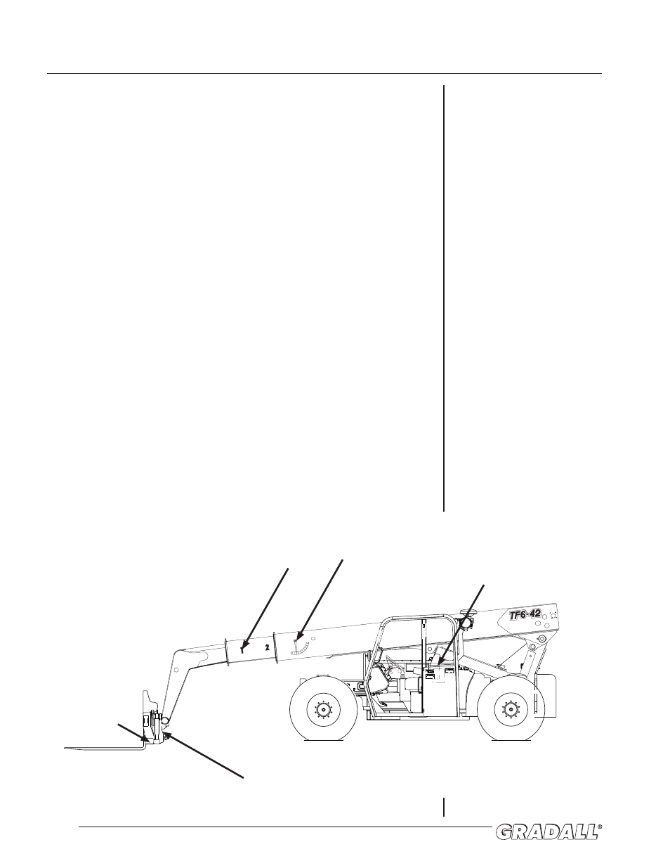
Figure 12-5:
Where to look on the machine
9114-3282
STAY CLEAR OF PINCH POINT AREA
ANYTIME ENGINE IS RUNNING.
BEING IN PINCH POINT AREA COULD
CAUSE SERIOUS INJURY OR DEATH.
9114-3282
STAY CLEAR OF PINCH POINT AREA
ANYTIME ENGINE IS RUNNING.
BEING IN PINCH POINT AREA COULD
CAUSE SERIOUS INJURY OR DEATH.
DO NOT GO NEAR LEAKS
C
10814B
* High pressure oil easily punctures skin causing serious injury, gangrene or death.
* If injured, seek emergency medical help. Immediate surgery is required to remove oil.
* Do not use finger or skin to check for leaks.
* Lower load or relieve hydraulic pressure before loosening fittings.
9114-3283
NO RIDERS PERMITTED ON HANDLER.
OPERATOR ONLY IN MACHINE
WHILE RUNNING.
RIDERS COULD FALL OFF MACHINE
CAUSING SERIOUS INJURY OR DEATH.
9114-3286
DIESEL FUEL IS FLAMMABLE
EXTINGUISH ALL OPEN FLAME AND
SMOKING MATERIALS WHEN REFUELING
INJURY OR DEATH COULD RESULT
FROM FIRE.
** unknown **
** unknown **
** unknown **
** unknown **
2
NO
1
R
7733-3027
FORK WEIGHT
STAMP
BOOM
EXTENSION
NUMBER
BOOM ANGLE
INDICATOR
ATTACHMENT
IDENTIFICATION PLATE
MACHINE SERIAL
NUMBER PLATE
(RIGHT WALL)
UNDERSTANDING RATED CAPACITY CHARTS