2 control components - installation, Ground control module, 2 control components - installation -2 – JLG SSV10 Service Manual User Manual
Page 56: Ground control module -2
SECTION 4 - CONTROL COMPONENTS
4-2
– JLG Lift –
3121187
4.2 CONTROL COMPONENTS -
INSTALLATION
IMPORTANT
BEFORE REMOVING ANY COMPONENT FROM THE ELECTRICAL
SYSTEM, DISCONNECT THE POSITIVE TERMINAL FROM THE
LEFT SIDE BATTERY.
Ground Control Module
The face of the Ground Control Module is visible from the
front of the machine and is located under the front cover. It
is mounted to a bracket on the base frame in front of the
hydraulic pump.
All electrical components on the machine operate directly
or indirectly through the Ground Control Module. The
module is currently programmed at the factory with the
machines operating profile. If replacing a Ground Control
Module the new module may require some programming
to enable any optional equipment.
For servicing and programming information for the
Ground Control Modudle, See Section 4.3, Ground Con-
trol Module - Service Procedure and Section 4.4, Ground
Control Module - Programming.
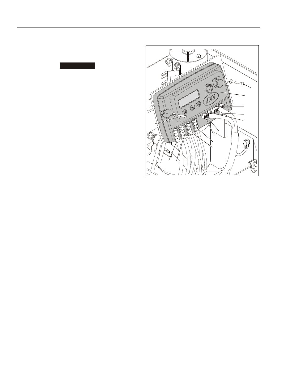
Ground Control Module - Installation
1. Ground Control Station Mod-
ule
2. Mounting Screws/Washers
(a)
3. P1 Connector (b)
4. P2 Connector (b)
5. P3 Connector (b)
6. P4 Connector (b)
7. P5 Connector (b)
8. From Inline Fuse (Battery +)
and To Traction Control Mod-
ule (+)
9. From Battery (–) and To
Traction Control Module (–)
10. To (+) Post on Hydraulic
Pump
11. To (–) Post on Hydraulic
Post
Note: (a) Apply Loctite #242 to screw threads on final assembly.
(b) To help seal unit from dust and moisture, apply electrical
contact grease CG60 (JLG Part# 3020038) to all electrical
connectors before assembly.
1
2
6
7
8
9
10
11
2
3
4
5