Checking/adjusting armature plate gap setting, Brake assembly installation – JLG SSV10 Service Manual User Manual
Page 43
SECTION 3 - BASE COMPONENTS
3121187
– JLG Lift –
3-15
Checking/Adjusting Armature Plate Gap Setting
1. First inspect that all parts of the brake assembly are
tight and secure. Tighten as necessary.
2. Inspect the brake for any debris which may be
lodged in the air gap between the armature plate
and magnetic coil when the brakes are ENGAGED
(brakes on); on either side of the friction disk when
the brake is RELEASED (brakes off). Clean and
remove debris as necessary.
3. With the brakes ENGAGED measure the air gap
between the armature plate and the magnetic coil
housing. The correct setting should be .006", how-
ever the brakes will operate properly if the measure-
ment is a minimum of .004" and a maximum of .010".
(See "Gap Setting" Illustration this Section)
4. If the air gap falls outside the maximum allowable
setting of .010" the friction disk has worn. To correct
this replace the disk with a new one.
5. If the air gap is below the minimum allowable setting
of .004", recheck the areas between the magnetic
coil housing, armature plate, friction disk and
mounting plate for debris. Clean as necessary.
Brake Assembly Installation
1. Secure the brake assembly to the drive motor hous-
ing using four (4) hex cap screws with washers.
Torque evenly to 44 in. lbs.
2. Reinstall the protective rubber boot over the drive
motor housing, secure the boot with the boot clamp.
3. Reconnect the drive motor/brake power wiring con-
nector to wiring harness connector.
4. Install the drive motor cover.
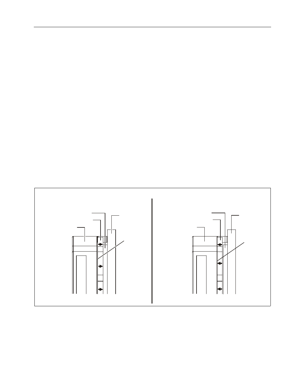
Gap Setting - Brake Engaged
(magnet not energized-springs engage plate against disk)
1. Magnetic Coil
3. Brake Disk(Engaged) 5. .006" Gap
2. Armature Plate 4. Mounting Plate
Gap Setting - Brake Disengaged
(magnet energized-plate compresses springs, disk rotates freely)
1. Magnetic Coil
3. Brake Disk (Free) 5. Plate Engaged -
2. Armature Plate 4. Mounting Plate Springs Compressed
3
3
2
2
1
1
5
5
4
4