Drive motor cover - installation, 3 drive and caster wheels, Rear) drive motor wheel - removal – JLG SSV10 Service Manual User Manual
Page 31: Drive motor wheel hub - installation, Drive motor cover - installation -3, 3 drive and caster wheels -3
SECTION 3 - BASE COMPONENTS
3121187
– JLG Lift –
3-3
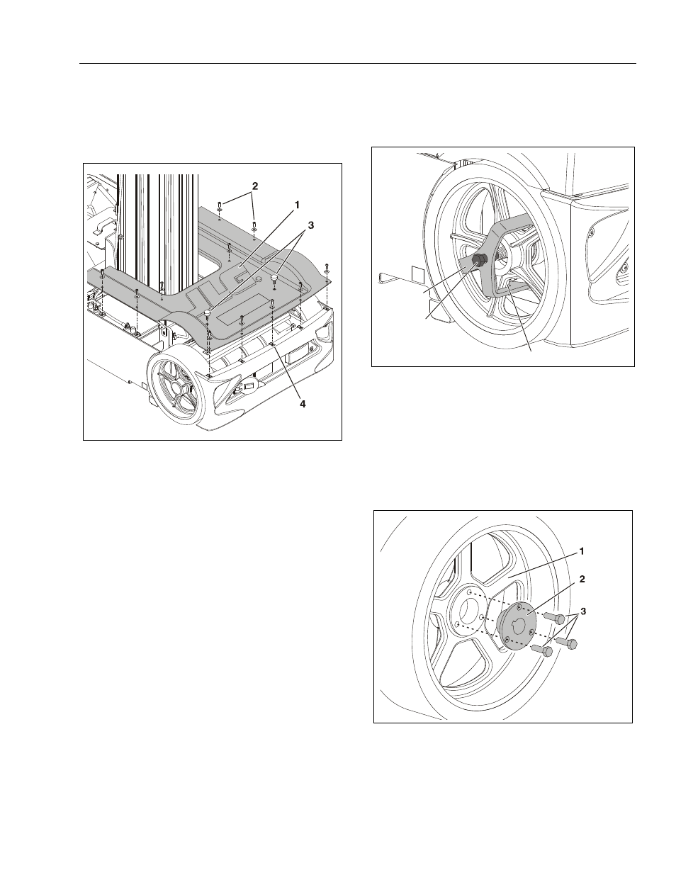
Drive Motor Cover - Installation
To gain access to the drive motor cover and screws, ele-
vate the platform.
3.3 DRIVE AND CASTER WHEELS
(Rear) Drive Motor Wheel - Removal
Drive Motor Wheel Hub - Installation
Drive Motor Cover Installation
1. Cover
2. Screws/Washers (a)
3. Platform Stop (a) (b)
4. U-Style Tapped Nuts
NOTE: (a) Apply Loctite #242 to threads before tightening.
(a) Height of the platform stops is set by installing two
(2) 5/16" dia. wide plain steel flatwashers under the
head of each stop, tighten securely.
Drive Wheel Removal Tool
1. Wheel Puller Tool (a)
2. Puller - Hex Head Screw (b)
3. Interface with back of
wheel spokes.
NOTE: First remove the Hub Cover, Cotter Pin, Shield and Nut.
(a) JLG Tool Part Number - 2915027
(b) Tighten in against the end of the drive motor shaft
until the wheel comes loose.
Drive Wheel Hub Installation
1. Rear Drive Wheel
2. Keyed Hub Insert
3. Hub Screws (a)
NOTE: (a) Apply loctite #271 to threads, torque to 19 ft. lb.
1
2
3