JLG SSV10 Operator Manual User Manual
Page 32
SECTION 3 - MACHINE OPERATION
3-4
– JLG Lift –
3121186
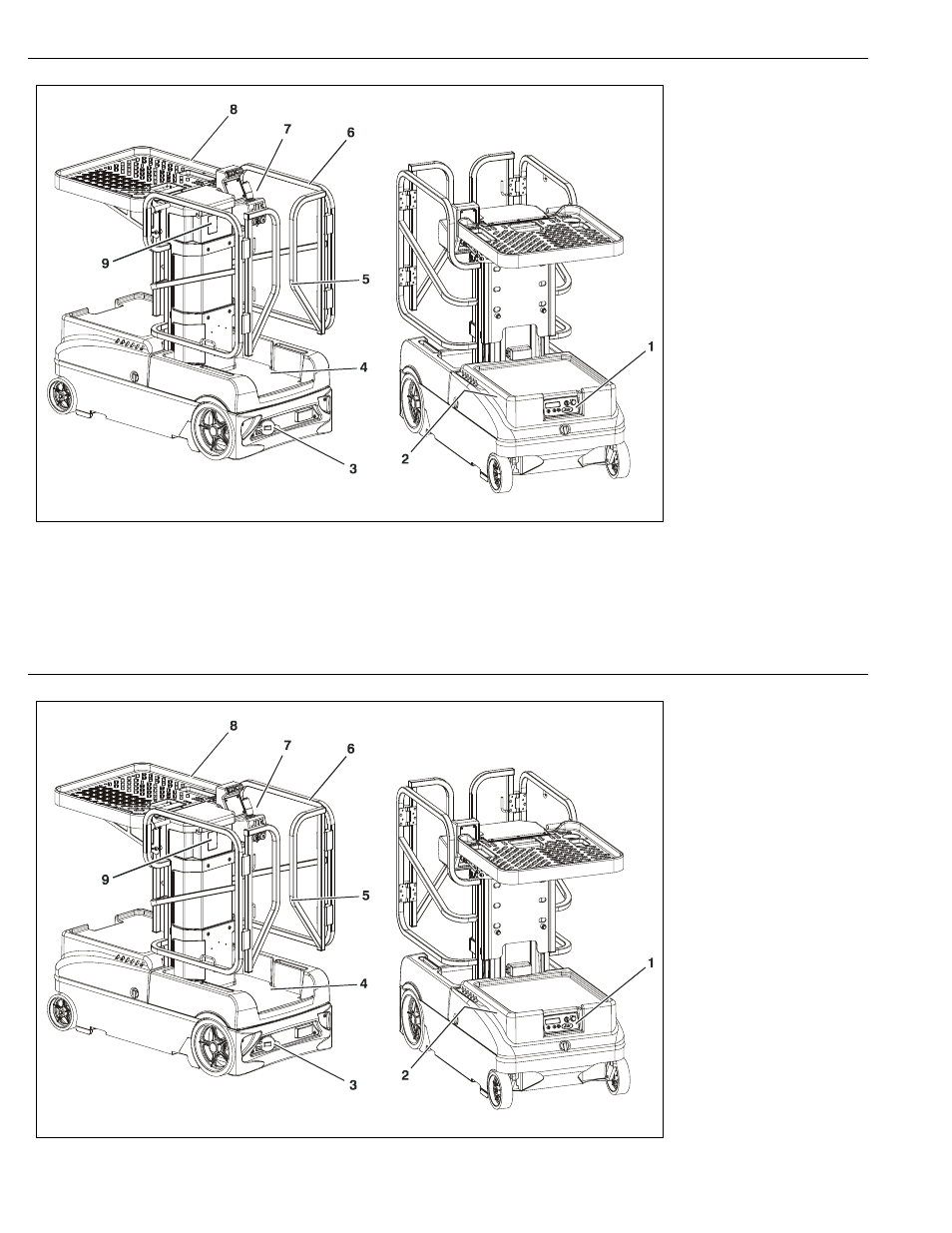
1. Ground Control Station
(Module) - (See page 3-10)
2. Platform Manual Descent
Valve (Located Under Hood)-
(See page 3-17)
3. Battery Charger AC Recepta-
cle and Charging Status LED
Indicators - (See page 3-5)
4. Platform Enable Foot Switch -
(See page 3-20)
5. Platform Entry Gate -
(See page 3-18)
6. Platform - (See page 3-18)
7. Platform Control Console -
(See page 3-21)
8. Material Handling Tray -
(See page 3-19)
9. (PSL) Programmable Secu-
rity Lock (OPTION) - (See
page 3-38)
Figure 3-1. Machine Operating Component Locations.
SECTION 3 - MACHINE OPERATION
3-4
– JLG Lift –
3121186
1. Ground Control Station
(Module) - (See page 3-10)
2. Platform Manual Descent
Valve (Located Under Hood)-
(See page 3-17)
3. Battery Charger AC Recepta-
cle and Charging Status LED
Indicators - (See page 3-5)
4. Platform Enable Foot Switch -
(See page 3-20)
5. Platform Entry Gate -
(See page 3-18)
6. Platform - (See page 3-18)
7. Platform Control Console -
(See page 3-21)
8. Material Handling Tray -
(See page 3-19)
9. (PSL) Programmable Secu-
rity Lock (OPTION) - (See
page 3-38)
Figure 3-1. Machine Operating Component Locations.