JLG G6-42A Service Manual User Manual
Page 87
4-13
G6-42A, G9-43A, G10-43A
Cab and Covers
4. Use a hoist or overhead crane and sling attached to
the cab. Carefully begin to align the cab with the
mounting holes in the frame. Stop and check that
wiring, hydraulic hoses, cables, etc., will not be
pinched or damaged as the cab is positioned.
Readjust the position of the sling as needed to help
balance the cab during installation.
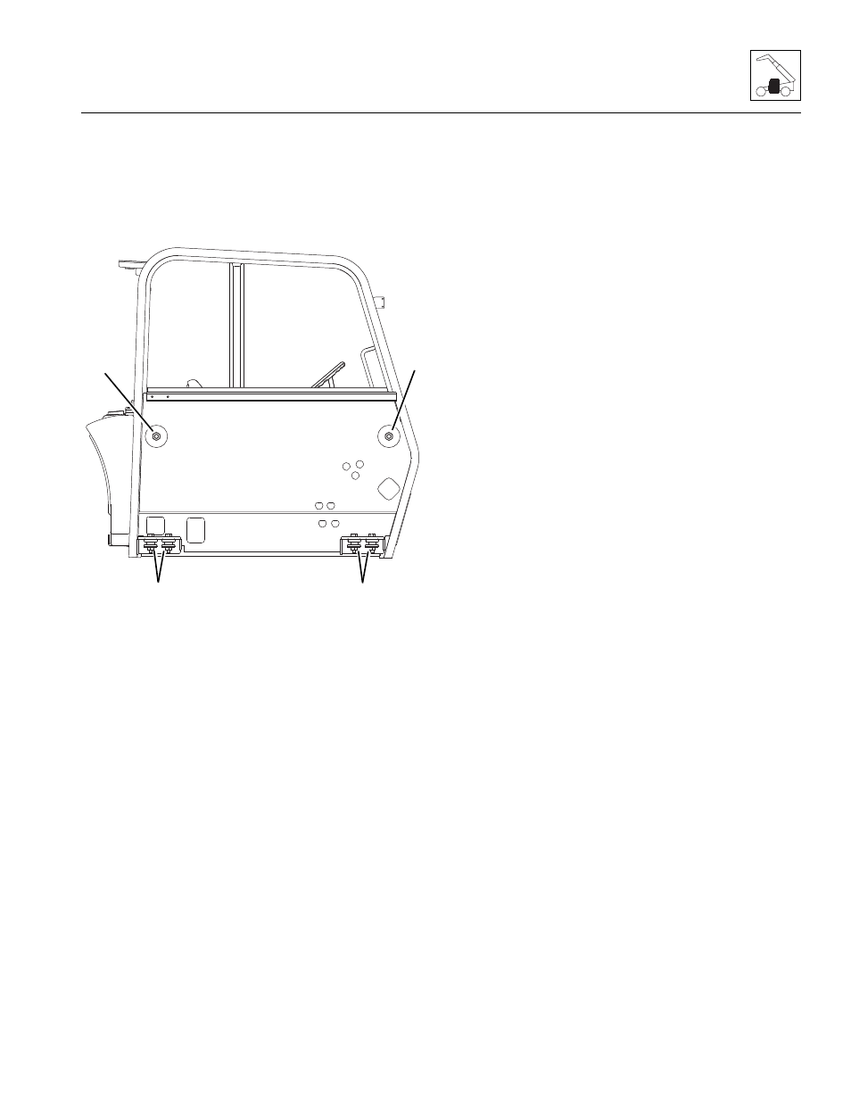
5. Install the four cab-to-frame mount bolts, washers and
nuts (18). Torque to 280-305 lb-ft (379-414 Nm).
6. Install the two cab side mount bolts washers and
nuts (17). Torque to 680-720 lb-ft (922-976 Nm).
7. Install the engine air filter and hydraulic oil reservoir
breather to their brackets at the top of the cab.
8. Install the throttle cable to the throttle pedal
assembly. Refer to Section 4.3.3, “Throttle Pedal.”
9. Pull all the hydraulic hoses and electrical wires
through the cab.
10. Uncap and reconnect the previously labeled
hydraulic hoses to their appropriate locations.
11. Reconnect the previously labeled electrical
connections to their appropriate locations.
12. For machines equipped with the heater option,
reconnect the heater hoses to the cab heater. Refer
to Section 4.3.7, “Heater/Air Conditioning System (if
equipped).”
13. Install the fuel tank to the cab. Refer to Section 7.6.2,
“Fuel Tank.”
14. Fill the cooling system completely with coolant,
allowing time for the coolant to fill the engine block.
The cooling system capacity is listed in Section 2.4,
“Fluid and Lubricant Capacities.”
15. Properly connect the battery.
16. Start the engine and check the operation of all controls.
Check for hydraulic fluid leaks. Check the hydraulic
fluid level in the tank and add fluid as required.
Note: When the engine is initially started, run it briefly at
low idle and check the machine for any visual sign of
fluid leakage. STOP the engine immediately if any
leakage is noted, and make any necessary repairs
before continuing.
17. Wait for the engine to cool and check the coolant
level. Add coolant to the overflow bottle as required
to bring the coolant to the proper level.
18. Install the mirrors and all other cab components as
needed, if removed.
19. Close and secure the engine cover.
20. Unblock the wheels.
21. Remove the Do Not Operate Tags from both the
ignition key switch and the steering wheel.
MY4170
18
18
17
17