3 push beam - extend/retract cylinder removal, Push beam - extend/retract cylinder removal, Caution – JLG G6-42A Service Manual User Manual
Page 46
Boom
3-8
G6-42A, G9-43A, G10-43A
6. Loosen and remove the tilt hose and auxiliary hose
retainers (7 & 8) from the front of the third boom
section.
7. Remove the right or left side wear pads, shims and
backing plates (9) from the rear of the third boom
section. Label and tag each set of wear pads being
removed.
8. Remove the top wear pads, shims and backing
plates (10) from the rear of the third boom section.
Label and tag each set of wear pads being removed.
9. Place a suitable sling around the third boom section.
Slowly pull the third boom section approximately
25% out of the second boom section. Lower the third
boom section onto a suitable support.
10. Remove all wear pads, shims and backing plates
(11) from the front inside of the second boom
section. Label and tag each set of wear pads being
removed.
11. Remove wear pad mounting plates (12) from the
front inside of the second boom section.
12. Relocate the sling or using two slings for better
stability, balance the third boom section and slowly
pull the third boon section out of the second boom
section. Lower the third boom section onto suitable
supports.
3.5.3
Push Beam - Extend/Retract Cylinder
Removal
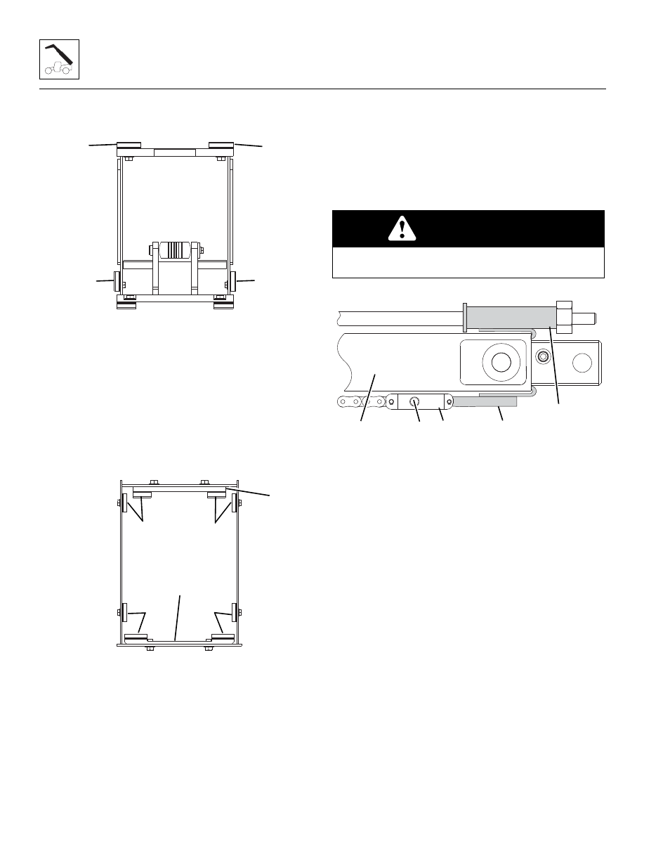
1. Loosen the Temporary Extend Chain Retention
Bracket (13) and push the push beam (14) forward
3-4 in (76,2-101,6 mm).
2. Attach the Temporary Extend Chain Retention
Bracket (15) between the chain clevis (16) and the
end of the push beam (14).
Note: Refer to Section 3.16, “Push Beam Temporary
Brackets,” for Temporary Extend Chain Bracket diagram.
3. Lift the push beam (14) to unload the clevis pin (17)
and remove the pin securing the clevis to the third
boom section.
4. Tighten the Temporary Extend Chain Retention
Bracket (13) to remove any slack in the extend chain.
5. Secure a rope or wire to the front of the push beam
and pull the push beam (14) towards the front of the
boom.
6. Support the push beam assembly with pry bars
using the access holes on each side of the third
boom section.
MY3890
9
10
10
9
MY3870
11
11
11
11
12
12
CAUTION
The complete push beam assembly weighs over
1,200 lb (545 kg).
MY4060
13
15
14
16
17