8 hydraulic cylinders, 1 general cylinder removal instructions, Hydraulic cylinders – JLG G6-42A Service Manual User Manual
Page 159: R to section, 8, “hydraulic cylinders, 1, “general cylinder removal instructions, General cylinder removal instructions
8-25
G6-42A, G9-43A, G10-43A
Hydraulic System
fittings to keep dirt & debris from entering the
hydraulic system.
7. Remove the bolts holding the outrigger control valve
to the frame.
b. Outrigger Valve Installation
1. Install the outrigger valve onto the machine frame.
2. Uncap and connect the previously labeled hydraulic
hoses to the outrigger valve.
3. Check the routing of all hoses, wiring and tubing for
sharp bends or interference with any rotating
members, and install tie wraps and/or protective
conduit as required. Tighten all hose clamps.
4. Properly connect the battery.
5. Start the engine and run at approximately 1/3-1/2
throttle for about one minute without moving the
machine or operating any hydraulic functions.
6. Inspect for leaks and check the level of the hydraulic
fluid in the reservoir. Shut the engine OFF.
Note: Check for leaks and repair as required before
continuing. Add hydraulic fluid to the reservoir as
needed.
7. Wipe up any hydraulic fluid spillage in, on, near and
around the machine, work area and tools.
8. Close and secure the engine cover.
9. Remove the Do Not Operate Tags from both the
ignition key switch and the steering wheel.
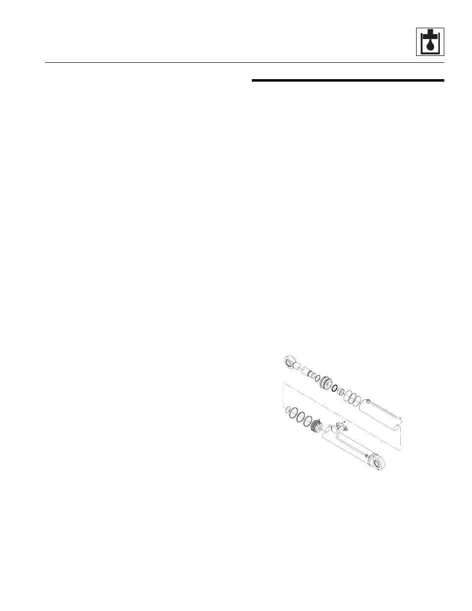
8.8
HYDRAULIC CYLINDERS
8.8.1
General Cylinder Removal
Instructions
1. Remove any attachment from the machine. Park the
machine on a firm level surface and fully retract the
boom. Allow sufficient work space around the
hydraulic cylinder being removed. Support the boom
if the lift/lower cylinder is being removed. Place the
travel select lever in (N) NEUTRAL, engage the park
brake, shut the engine OFF and chock wheels.
2. Place a Do Not Operate Tag on both the ignition key
switch and the steering wheel.
3. Open the engine cover. Allow the system fluids to
cool.
4. Label, disconnect and cap or plug hydraulic hoses in
relation to the cylinder.
5. Attach a suitable sling to an appropriate lifting device
and to the cylinder. Make sure the device used can
actually support the cylinder.
6. Remove the lock bolt and/or any retaining clips
securing the cylinder pins. Remove the cylinder pins.
7. Remove the cylinder.
8. Wipe up any hydraulic fluid spillage in, on, near and
around the machine, work area and tools.
a. General Cylinder Disassembly
1. Clean the cylinder with a suitable cleaner before
disassembly. Remove all dirt, debris and grease
from the cylinder.
2. Clamp the barrel end of the cylinder in a soft-jawed
vise or other acceptable holding equipment if
possible.
MZ0400