7 heater/air conditioning system (if equipped), Heater/air conditioning system (if equipped) – JLG G6-42A Service Manual User Manual
Page 84
Cab and Covers
4-10
G6-42A,G9-43A, G10-43A
4.3.7
Heater/Air Conditioning System
(if equipped)
a. Heater Assembly Removal
1. Park the machine on a firm, level surface, level the
machine, fully retract the boom, lower the boom,
place the travel select lever in the (N) NEUTRAL
position, engage the park brake and shut the engine
OFF.
2. Place a Do Not Operate Tag on both the ignition key
switch and the steering wheel.
3. Open the engine cover. Allow the system fluids to
cool.
4. Properly disconnect the battery.
5. Place a suitable container beneath the radiator.
Slowly turn the radiator cap to the first stop, and
allow any pressure to escape. Remove the radiator
cap.
6. Place a funnel at the base of the radiator to channel
the drained coolant into the container. Loosen the
drain petcock and allow the coolant to drain.
7. Transfer the coolant to a container with a cover, and
label as “Used Antifreeze.” Dispose of the used
coolant at an approved recycling facility.
8. Tighten the radiator drain petcock.
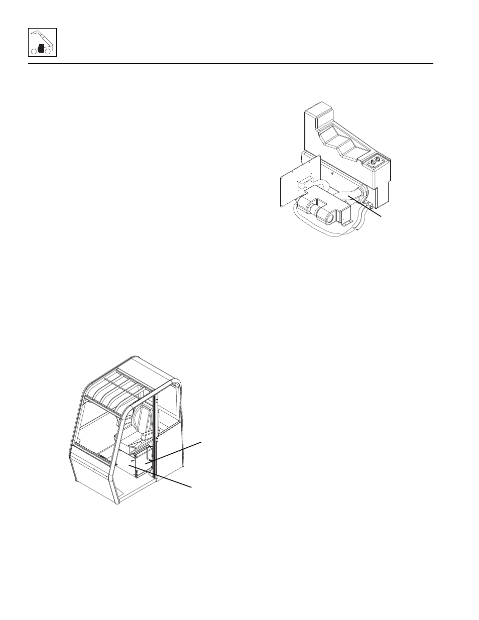
9. Remove the bolts that secure the seat to the cab.
Remove the seat.
10. Remove the bolts securing the front plate (11) to the
seat riser weldment (12).
11. Remove the bolts securing the seat riser weldment
to the cab. Remove the riser weldment.
12. Loosen the hose clamps, label and disconnect the
heater hoses (13). Cap or plug the hoses to prevent
debris from entering the heater system.
13. Label and disconnect any electrical connections.
14. Remove the bolts securing the heater assembly to
the cab. Remove the heater assembly.
b. Heater Assembly Installation
1. Position the heater assembly to its original orientation
in the cab. Secure with the previous hardware.
2. Connect the previously labeled electrical
connections.
3. Connect the previously labeled heater hoses to their
appropriate locations.
4. Install the seat riser weldment.
5. Install the front plate to the seat riser weldment.
6. Install the cab seat.
7. Fill the cooling system completely, allowing time for
the coolant to fill the engine block. The cooling
system fluid and capacity is listed in Section 2.4,
“Fluid and Lubricant Capacities.”
8. Properly connect the battery.
Note: When the engine is initially started, run it briefly at
low idle and check the machine for any visual sign of
fluid leakage. STOP the engine immediately if any
leakage is noted, and make any necessary repairs
before continuing.
9. Wait for the engine to cool and check the coolant
level. Add coolant as required to bring the coolant to
the proper level.
10. Close and secure the engine cover.
11. Remove the Do Not Operate Tags from both the
ignition key switch and the steering wheel.
MY0190
11
12
MY0200
13