JLG G6-42A Service Manual User Manual
Page 57
3-19
G6-42A, G9-43A, G10-43A
Boom
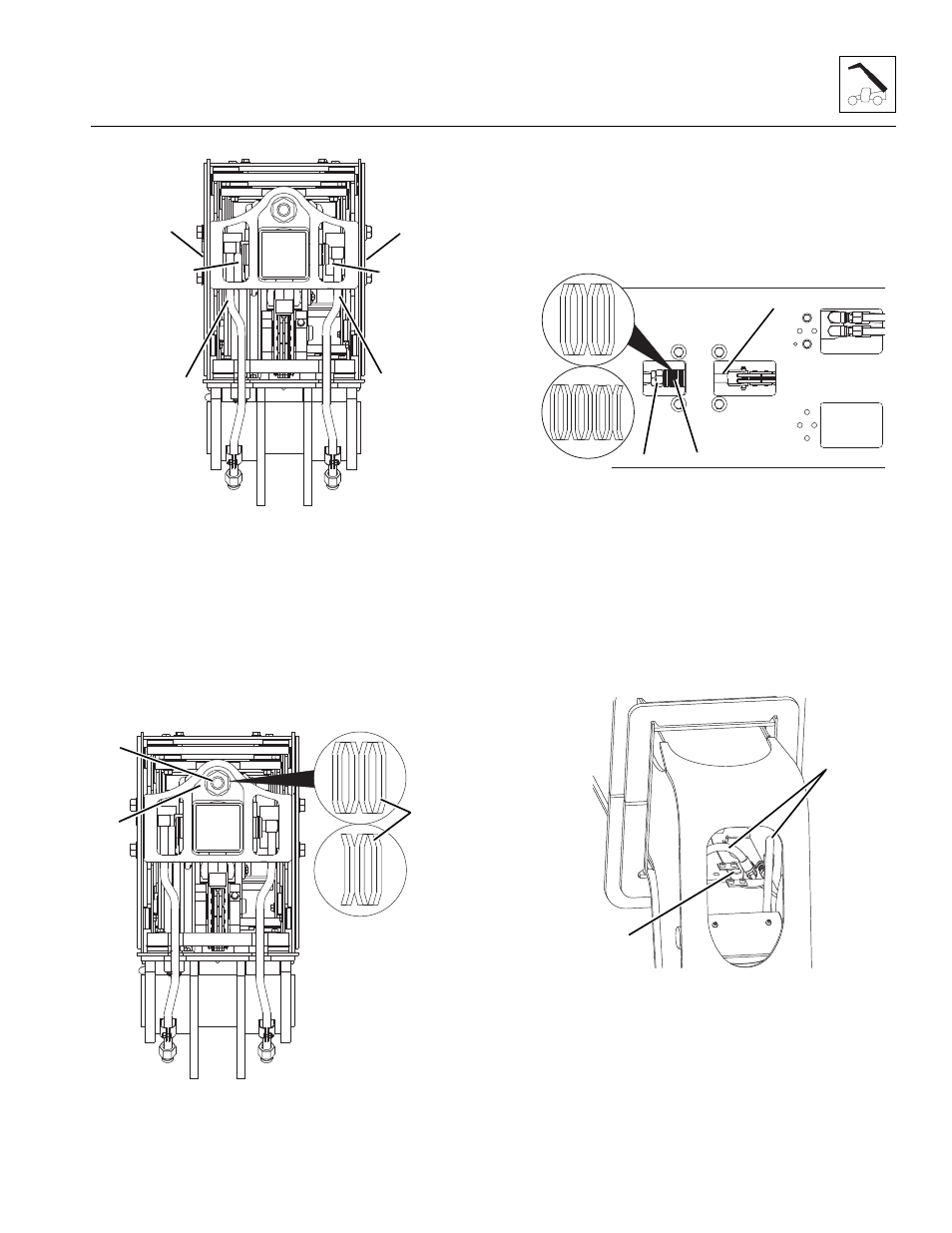
13. Install both push beam pins (10) being careful to
align the pin mounting bolt holes.
Note: Disconnecting one or both extend/retract
hydraulic tubes (11) may be required to gain access to
the hose guide mounting bolts. After installing both hose
guides, re-connect one or both extend/retract hydraulic
tubes BEFORE preceding.
14. Install the tilt cylinder hose guide (12) and the
auxiliary hose guide from the rear of the third second
section.
Note: Note the position of the belleville washers for
reassembly.
15. Install the belleville washers (13) to the extend chain
anchor (14) as previously removed at the rear of the
first boom section.
16. Install the adjustment and lock nut, (15) to the
extend chain anchor (14) at the rear of the first boom
section.
17. Remove the rope or wire from the retract chain (16).
18. Install the belleville washers (17) to the retract chain
clevis (16) as previously removed at the bottom front
of the first boom section.
19. Install the adjustment and lock nut (18) to the retract
chain clevis (16) at the bottom front of the first boom
section.
Note: Note the position of the belleville washer for
reassembly.
20. Install both hose retainer brackets (19).
21. Remove the plugs and caps from the tilt hoses and
auxiliary hoses.
22. Connect both tilt hoses (20) and both auxiliary hoses
(not shown) to the hose retainer brackets (19) at the
bottom front inside the boom.
23. Properly connect the battery.
MAL1290
12
12
10
10
11
11
MAL2660
13
15
14
G6-42A
G9-43A
G10-43A
MAL2670
17
18
16
G6-42A
G9-43A
G10-43A
MAL1310
20
19