2 service brake pedal, Service brake pedal – JLG G6-42A Service Manual User Manual
Page 80
Cab and Covers
4-6
G6-42A,G9-43A, G10-43A
6. Remove the steering wheel (2), disconnect and
remove the travel select lever (3), disconnect the
instrument panel harness connector (4).
7. Remove the steering assembly through the dash
panel opening.
8. Support the steering valve, and remove the four hex-
head capscrews and four lockwashers.
Note: DO NOT disassemble the orbitrol valve. The
orbitrol valve is not serviceable and must be replaced in
its entirety, if defective.
b. Orbitrol Valve Installation
1. Secure the steering valve to the steering column
with four hex-flange capscrews and four
lockwashers.
2. Install the steering column through the dash panel
opening. Position steering valve to its original
orientation in the cab.
3. Install the travel select lever, connect the instrument
panel harness connector, install the steering wheel
assembly. Torque the steering wheel nut to 29-34 lb-ft
(39-46 Nm).
4. Install new o-rings into the steering valve fittings.
Lubricate the o-rings with clean hydraulic oil.
5. Uncap and connect the previously labeled load
sense hose to the steering valve.
6. Uncap and connect the remaining previously labeled
four hoses to the steering valve.
Note: If necessary, install the main dash panel. Refer to
Section 9.12.1, “Analog Gauges.”
7. Properly connect the battery.
8. Carefully examine all connections one last time
before engine start-up. Rectify any faulty conditions.
9. Start the engine and check the operation of steering
system. Check for hydraulic fluid leaks. Check the
hydraulic fluid level in the tank and add fluid as
required.
10. Close and secure the engine cover.
11. Remove the Do Not Operate Tags from both the
ignition key switch and the steering wheel.
c. Steering Test
Conduct a pressure check of the steering hydraulic
circuits at the main control valve. Refer to Section 8.3.1,
“Pressure Checks and Adjustments.”
4.3.2
Service Brake Pedal
a. Brake Valve Removal
Refer to Section 8.7.2, “Service Brake Valve,” for removal
information.
b. Brake Valve Installation
Refer to Section 8.7.2, “Service Brake Valve,” for
installation information.
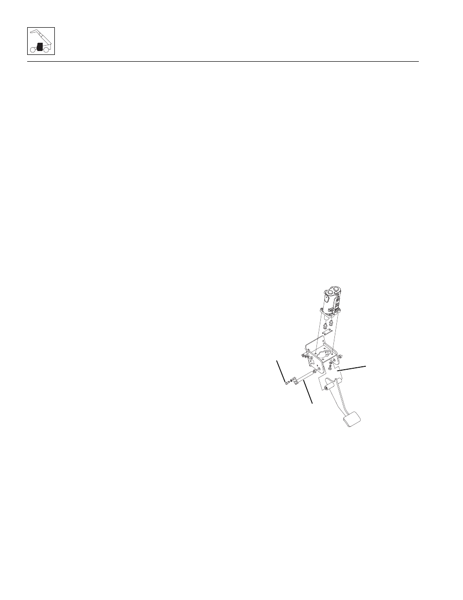
c. Service Brake Pedal Removal
1. Park the machine on a firm, level surface, level the
machine, fully retract the boom, lower the boom,
place the travel select lever in the (N) NEUTRAL
position, engage the parking brake and turn the
engine OFF.
2. Place a Do Not Operate Tag on both the ignition key
switch and steering wheel.
3. Open the engine cover. Allow the system fluids to
cool.
4. Properly disconnect the battery.
5. Remove the bolt and lockwasher (1) securing the
service brake pedal pivot pin (2).
6. Pull the pivot pin from the service brake pedal
bracket (3).
7. Remove the service brake pedal from the cab.
d. Service Brake Pedal Installation
1. Position the service brake pedal in its mounting
location within the cab.
2. Secure the brake pedal into position with the pivot pin.
MY0141
1
2
3