2 manually resetting the park brake, Manually resetting the park brake – JLG G6-42A Service Manual User Manual
Page 101
5-13
G6-42A, G9-43A, G10-43A
Axles, Drive Shafts, Wheels and Tires
Note: After the machine has been towed to a secure
location, reactivate the parking brake. Carefully follow
the procedures from start to finish. Consult your local
JLG distributor or the JLG Service Department if you are
unsure about any part of the procedure, or for specific
instructions concerning your particular situation.
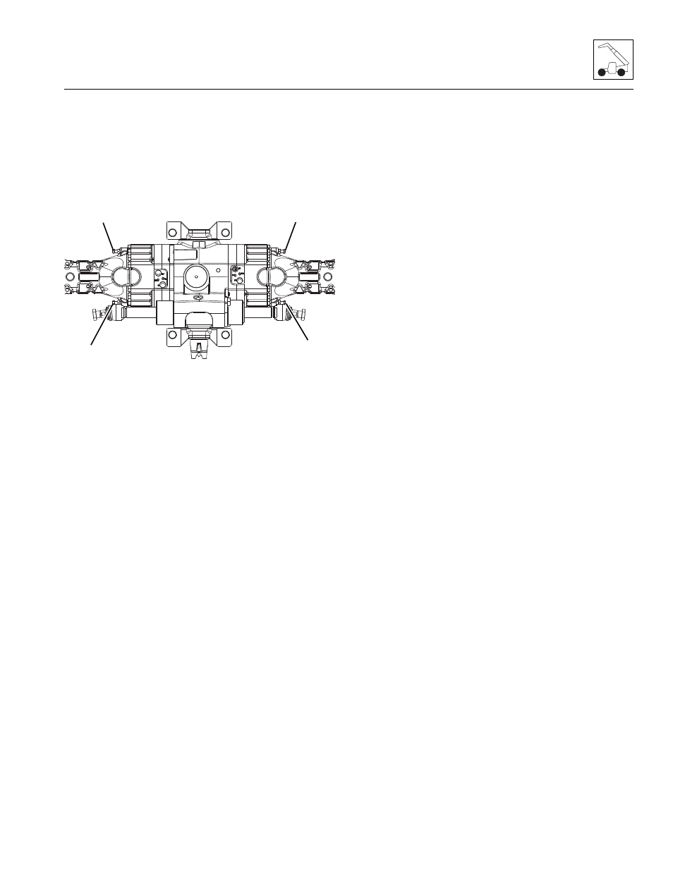
b. S/N 0160000847 & After
1. Loosen the nuts of the screws (7) for the manual
release of the braking units. Draw the nuts back
approximately 0.25 in (6 mm).
2. Tighten the screws until they are gently seated on
the driving plate
3. Carefully tighten each release screw a 1/4 turn at a
time in sequence until all have been turned on full
turn 360°.
4. Repeat steps 1 thru 3 for the other side of the
differential.
Note: After the machine has been towed to a secure
location, reactivate the parking brake. Carefully follow
the procedures from start to finish. Consult your local
JLG distributor or the JLG Service Department if you are
unsure about any part of the procedure, or for specific
instructions concerning your particular situation.
5.7.2
Manually Resetting the Park Brake
Note: Block the wheels of the machine BEFORE
attempting to reset the machine’s park brake. Once
the park brake is released the machine’s park brake
AND service brakes are inoperable.
a. Before S/N 0160000847
1. Loosen each release screw, only 1/4 turn at a time,
in sequence, until each screw has lost contact with
the guide pin.
2. Back out each screw until it bottoms out against the
stop.
3. Install the previously used plugs over each release
screw.
4. Repeat steps 1 thru 3 for the other side of the
differential.
5. After repairs to the machine have been made, start
the machine and check the park brake and service
brakes for proper function.
b. S/N 0160000847 & After
1. Loosen each release screw, only 1/4 turn at a time,
in sequence, until each screw has lost contact with
the guide pin.
2. Remove the screws along with the nuts and seals.
Replace the seals, lubricate the screws with a
silicone-based grease and re-install the screws
along with the nuts.
3. Adjust the nut of the screw heads in relation to the
arm by 1.26 in (32 mm).
4. Repeat steps 1 thru 3 for the other side of the
differential.
5. After repairs to the machine have been made, start
the machine and check the park brake and service
brakes for proper function.
MZ1020
7
7
7
7