7 third boom section assembly, 8 fourth boom section installation, Third boom section assembly – JLG G12-55A Service Manual User Manual
Page 46: Fourth boom section installation
Boom
3-12
G10-55A, G12-55A
13. Install guide bracket (16) P/N using the previously
removed hardware (17). Torque as required.
3.5.7
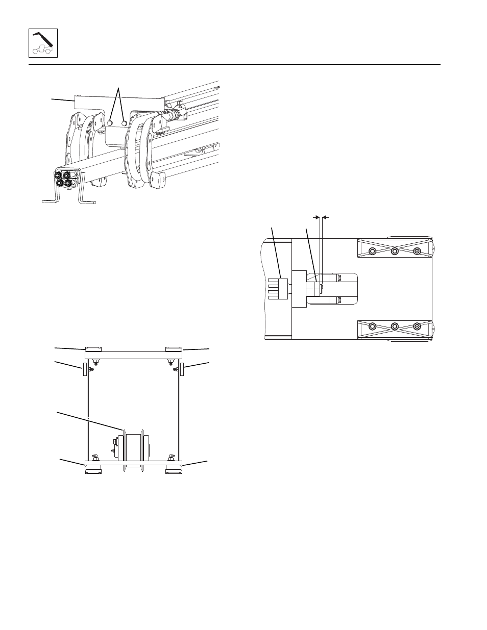
Third Boom Section Assembly
Note: Inspect and lubricate all extend and retract chains
before re-assembly. Refer to Section 3.12.1, “Boom
Chain Inspection,” for detailed information.
Note: Using a straight bar approximately 40 in
(1041 mm) long will aid in the installation of the wear
pads located on the inside front of each boom section.
1. Place the third boom section onto suitable supports.
2. Install the previously removed chain roller (1) at the
rear of the third boom section. Insert the mounting
pin, retainer plate and hardware. Torque as required.
3. Install the previously removed wear pads and
spacers (2) at each side rear of the third boom
section. Snug mounting bolts. Shim as needed
AFTER all boom sections are installed to maintain a
0.070 - 0.130 in (1,78 - 3,30 mm) gap between the
boom sections.
4. Install the previously removed wear pads (3) at the
bottom rear of the third boom section. Snug
mounting bolts. Shim as needed AFTER all boom
sections are installed to maintain a 0.070 - 0.130 in
(1,78 - 3,30 mm) gap between the boom sections.
5. Install the previously removed wear pads and
spacers (4) at top rear of the third boom section.
Snug mounting bolts. Shim as needed AFTER all
boom sections are installed to maintain a 0.070 -
0.130 in (1,78 - 3,30 mm) gap between the boom
sections.
6. Shims may be required to maintain a 0.070 - 0.130
in (1,78 - 3,30 mm) gap at the top rear of the third
boom section.
7. Install the previously removed extend chain
assemblies and clevises (5) at the top rear of the
third boom section. Allow 0.250 in (6,35 mm)
between the end of the clevis (5) and the face of the
lock nut (6). Torque lock nut to 100 lb-ft (135 Nm).
3.5.8
Fourth Boom Section Installation
Note: Using a straight bar approximately 40 in
(1041 mm) long will aid in the installation of the wear
pads located on the inside front of each boom section.
1. Clean and lubricate the bottom of the fourth boom
section where the wear pads of the third boom
section contact the fourth boom section.
2. Place the sling, or two slings for better stability,
around the fourth boom section and slowly insert the
fourth boom section into the third boom section
being careful not to damage any surrounding
components.
MY3480
17
16
MY3500
2
1
2
3
3
4
4
MY3630
C
6
5