JLG G12-55A Service Manual User Manual
Page 175
9-33
G10-55A, G12-55A
Electrical System
2. Place a Do Not Operate Tag on both the ignition key
switch and the steering wheel, stating that the
machine should not be operated.
3. Open the engine cover. Allow the system fluids to
cool.
4. Properly disconnect the battery.
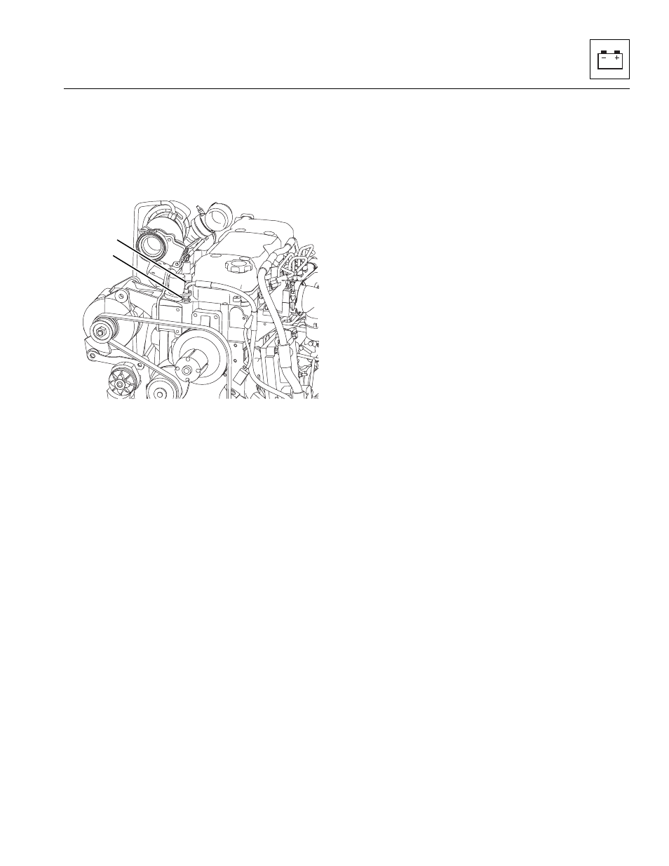
5. Unplug the engine coolant temperature sender
connector (1) from the wiring harness connector.
6. The engine coolant temperature sender (2) is
located near the upper radiator hose thermostat
housing and threaded into the engine block.
Remove the sender.
b. Engine Coolant Temperature Sender Inspection
and Replacement
Inspect the sender and the wiring harness connector
terminals for continuity. Replace a defective or faulty
sender with a new part.
c. Engine Coolant Temperature Sender Installation
and Testing
1. Thread the engine coolant temperature sender into
the engine block snugly, then connect the sender
connector to the wiring harness connector.
2. Properly connect the battery.
3. Check for proper coolant level.
4. Start the engine, allow it to reach operating
temperature and observe the operator’s instrument
cluster for warning indication. If the sender is not
defective, the problem could be elsewhere; possibly
in a shorted wire, improper-running engine, improper
or low coolant, obstructed or faulty radiator, coolant
pump, loose fan belt, defective instrument display,
etc.
5. Close and secure the engine cover.
6. Remove the Do Not Operate Tags from both the
ignition key switch and the steering wheel.
MY4620
2
CUMMINS ENGINE SHOWN
1