JLG G12-55A Service Manual User Manual
Page 41
3-7
G10-55A, G12-55A
Boom
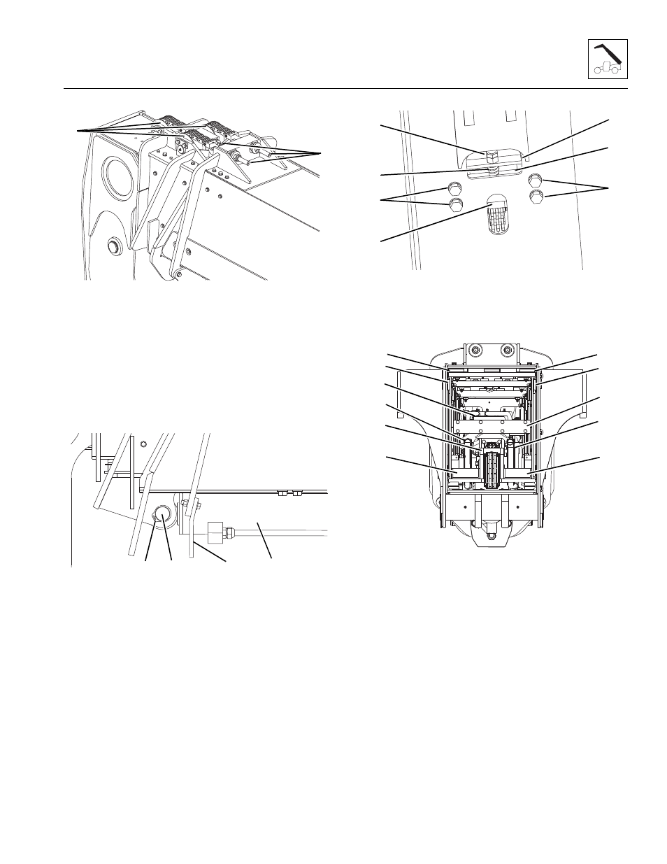
17. Pull the three extend chain clevises (9) off of each
chain roller (14) and lay each assembly on the third
and fourth boom sections respectively.
Note: It may be necessary to remove the extend chain
rollers to help in the removal of the top wear pads.
18. Verify all fittings, tubes and hoses are properly
capped and /or plugged.
19. Extend the second boom section to access the
retract chain adjusting block.
20. Remove the extend/retract cylinder support (15)
from the front of the first boom section.
21. Support the extend/retract cylinder (16) with a
suitable sling.
22. Remove the retaining clips (17) from each side of
the extend/retract cylinder rod.
23. Remove the extend/retract cylinder rod mounting pin
(18).
24. Lower the front of the extend/retract cylinder to a
secured block on top of the frame. Do Not use the
engine hood for support.
25. Remove the adjusting nut and lock nut (19), retract
chain & clevis (20), spring stop (21) and spring (22).
Loosen bolts (23) and adjusting block (24).
26. Properly disconnect the battery.
27. At the rear of the boom, remove both hose sheave
covers (25).
28. Unbolt the hose carrier bracket (26) from the rear of
the second boom section and the hose carrier.
29. Pull the hose carrier (27) back to gain access to the
tilt hose (28) and the auxiliary hose (29)
connections.
30. Disconnect the tilt hoses, auxiliary hoses and if
equipped, the electrical connector at the rear of the
hose carrier. Label, plug and cap all hydraulic
connections to prevent dirt and debris from entering
the hydraulic system.
31. Push hose carrier (27) as far forward as possible.
Note: Tag each wear pad, spacer, shim and hardware
from each location. Note the location of any grease fitting
(if equipped) on each wear pad.
MY3440
14
9
MY4120
15
16
17
18
MY3540
19
24
22
23
20
21
23
MY3420
30
25
31
25
30
31
32
29
26
28
27