9 inclinometer switch, Inclinometer switch – JLG G12-55A Service Manual User Manual
Page 178
Electrical System
9-36
G10-55A, G12-55A
b. Fuel Level Circuit Tests
If the fuel level sender (8) is suspected of giving a false
reading, perform the following checks:
1. If the fuel level indicator needle does not move,
check the fuel tank for fuel.
2. Check for loose or defective wiring, faulty ground
connections, and corrosion on the fuel tank sender
and wiring lead.
3. If the fuel level indicator needle does not move after
the ignition key switch is turned to the RUN position,
use a test lamp to determine whether current is
flowing from the ignition switch to the fuel level
sender.
4. If the fuel level indicator does not move and a faulty
or defective fuel level sender in the fuel tank has
been ruled out, and in addition, wiring and
connectors have been checked and ruled out, the
fuel level indicator is defective and must be
replaced.
5. Check that the ignition terminal has current and that
the fuse in the fuse panel is not blown.
6. Check for broken, shorted, frayed, disconnected or
damaged wiring between the fuel level indicator
wiring at the cab, fuse and relay panel, ignition key
switch, and from the fuel level sender on the fuel
tank through the wiring in the cab.
7. Check the fuel level sender. A defective fuel level
sender in the fuel tank may also prevent the fuel
level indicator from moving. Refer to Section 9.5,
“Electrical System Schematics,” for further
information.
9.10.9
Inclinometer Switch
G10-55A Before S/N 0160038543
G12-55A Before S/N 0160038542
a. Inclinometer Switch Removal
1. Park the machine on a firm, level surface, level the
machine, fully retract the boom, raise and support
the boom, place the transmission control lever in
(N) NEUTRAL, engage the park brake and shut the
engine OFF.
2. Place a Do Not Operate Tag on both the ignition key
switch and the steering wheel, stating that the
machine should not be operated.
3. Open the engine cover. Allow the system fluids to
cool.
4. Properly disconnect the battery.
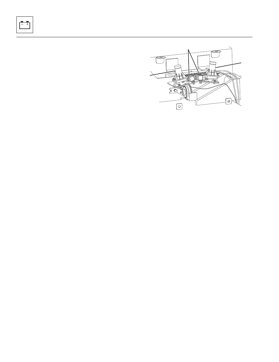
5. Remove the inclinometer switch protective cover.
6. Unplug and label the inclinometer switch connector
(9) from the wiring harness connector.
7. Remove the hardware securing the inclinometer
switch (10) to the machine frame.
b. Inclinometer Switch Installation
1. Install the inclinometer switch to the machine frame
with the previously used hardware.
2. Connect the previously labeled wires to the
inclinometer switch.
3. Install the inclinometer switch protective cover.
4. Properly connect the battery.
5. Close and secure the engine cover.
6. Start the engine. Fully retract and level the boom
and level the frame.
7. Locate a 12” curb and drive the left front and left rear
tires onto the curb. Sway the machine to the right.
When the frame is out of level by 15°, the machine
will automatically sway back to 14.7°.
8. Repeat step 7 for the right side of the machine.
9. Remove the Do Not Operate Tags from both the
ignition key switch and the steering wheel.
MY1311
9
10
10